Subject to Export Control, see Cover Page for details. 2-45
E. RF Power Meter Calibration (cont)
34. Press the F5 “Next” Key to move to the next cal point.
NOTE
Index: numbers increment by one and the Target dBm: indicates the next cal
point level.
35. Repeat Steps 32 to 34 until the Index returns to 0.
36. Set the RF Signal Generator to RF OFF.
37. Set the RF Amplifier to OFF.
38. Press the F3 “Save” Key.
39. Cycle power on the Test Set.
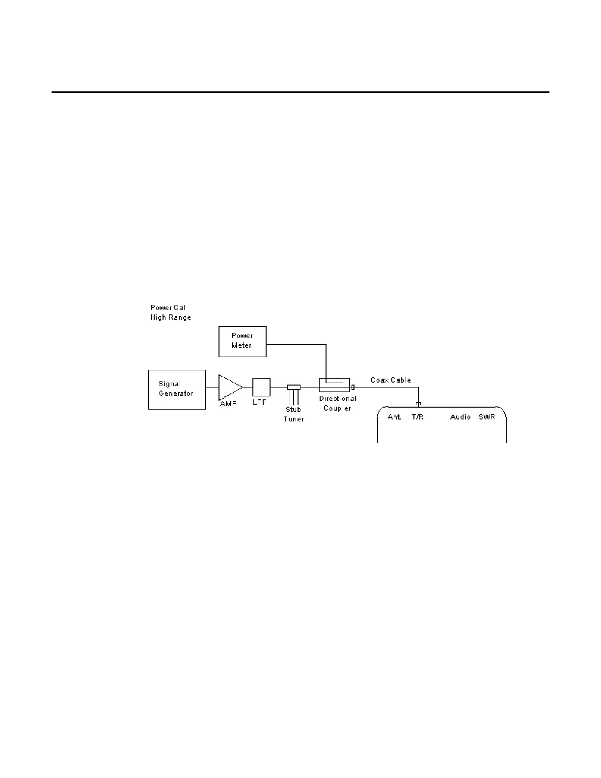
RF POWER CAL HIGH RANGE
40. Connect test equipment:
41. Set the RF Signal Generator to 500 MHz, CW, -50 dBm and RF OFF.
42. Set the RF Power Meter to 500 MHz, Relative OFF and Offset value to 500 MHz coupled
port attenuation recorded in Step 7.
43. Set RF Power Amplifier Gain to maximum, ALC to OFF and Power to OFF.
44. With the System Menu displayed, press the F4 “Selftest” Key to display the Self Test
Menu.
45. Press the 3 Key to display the Calibration Screen.
46. Enter the Calibration Password (30203). Press the F1 “Done” Key to display the Internal
Calibration Menu.
47. Press the 4 Key (POWER CAL HIGH RANGE).
48. Press the F4 “Zero” Key and follow the instructions on the Test Set display.
NOTE
Corrected A2D value is 0 (± 5).