2-62 Subject to Export Control, see Cover Page for details.
D. Power Supply Assy (62A1A1)
DESCRIPTION
This procedure covers: Remove. Install.
PRELIMINARY PROCEDURES
Remove Battery (para 2-4A).
Open Case Assy (para 2-4C).
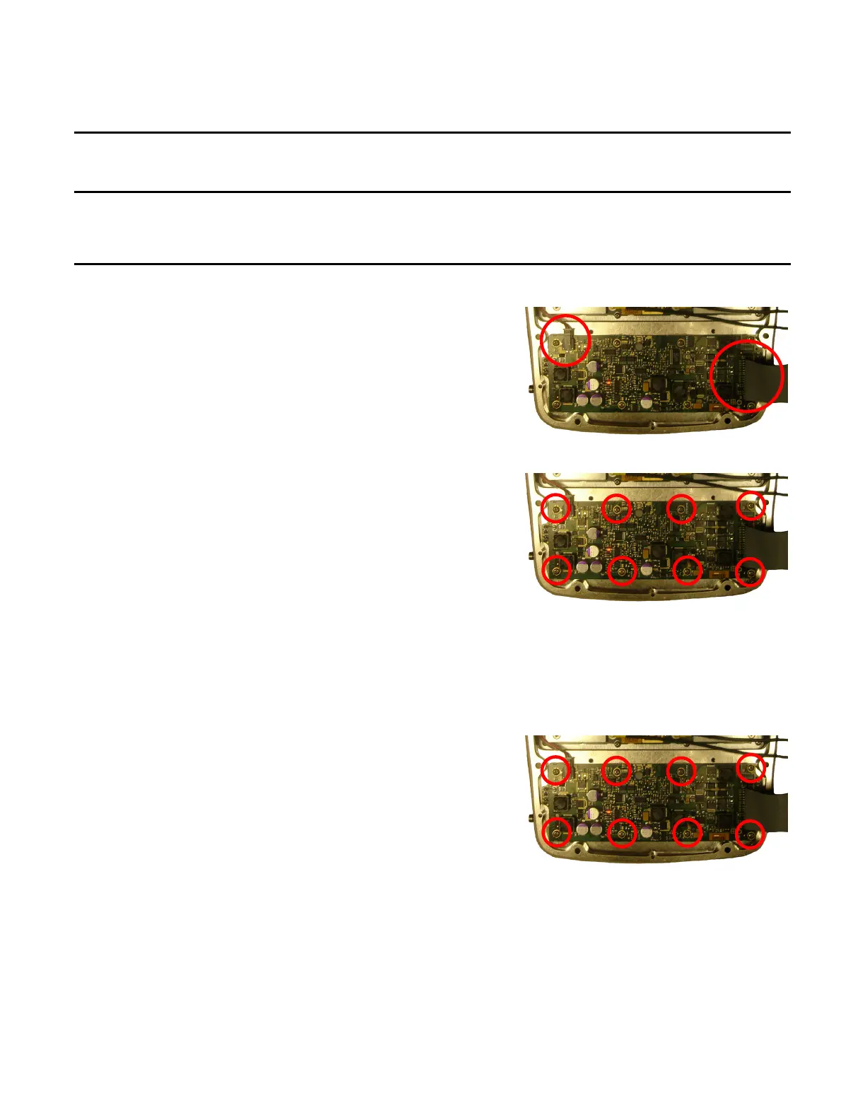
REMOVE
1. Disconnect wire cable and ribbon cable.
2. Remove eight screws.
3. Remove Power Supply PCB Assy.
INSTALL
1. Install Power Supply PCB Assy.
2. Install eight screws (6 in/lbs.).