27
Connecting to gas
CAUTION: ENSURE THAT THE APPLIANCE IS ISOLATED
FROM ELECTRIC SUPPLY
The appliance must be installed by connection to rigid
pipework, which should not be less than 15 mm diameter.
Conection is made to the ½” BSP female threaded tting
located just below the hotplate level on the rear left-hand
side of the appliance attached to the gas regulator.
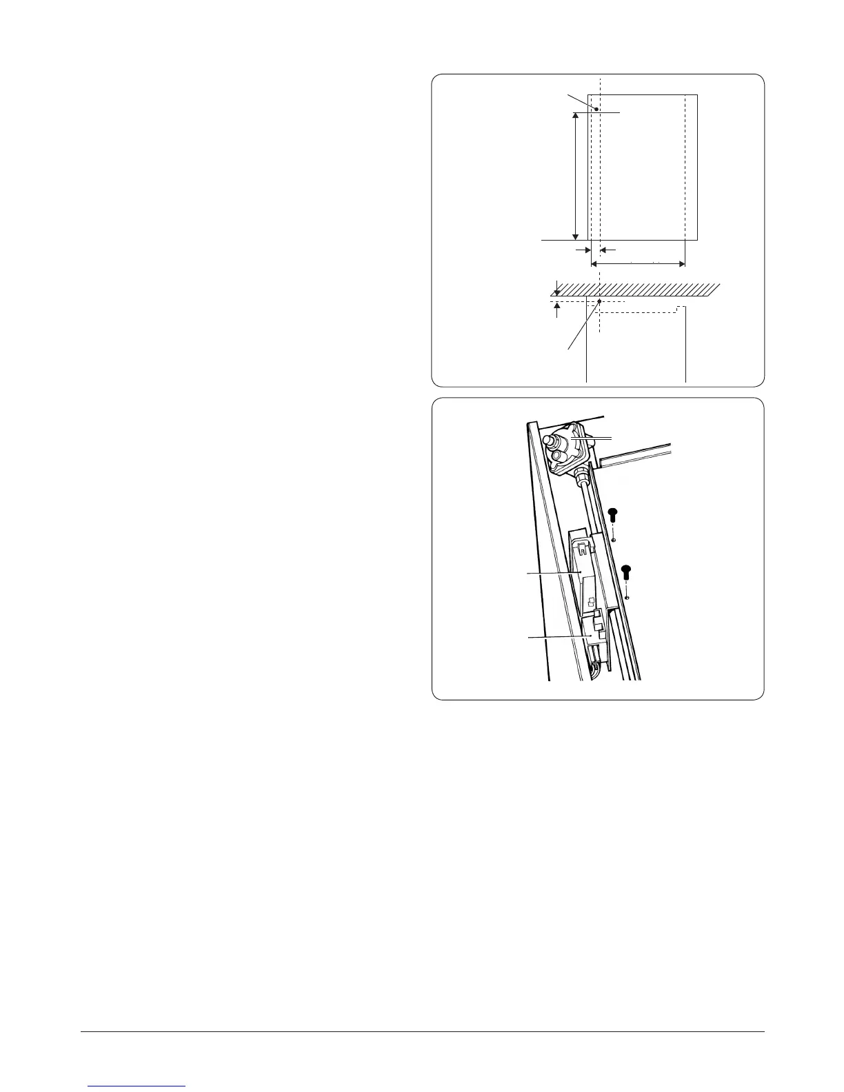
1. Mark o approximate position on wall for gas supply to
the appliance (Fig. 13.4). Dimensions N and O (See Fig.
10.1).
2. Isolate the gas supply and connect pipework as required
up to the position marked.
3. Check for gas tightness after connecting the gas supply.
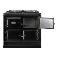
4. Make the nal gas connection to the appliance into the
½” BSP female threaded tting located just below the
hotplate level attached to the gas regulator (See Fig.
13.5).
5. Check for gas tightness after connecting the gas supply.
6. To conrm the pressure setting, follow the “Pressure
testing” page 30 procedure.
DESN 511792
SPARK
GENERATOR
TERMINAL
BLOCK
GAS REGULATOR
800 mm
(31 ½”)
580 mm
(22 /”)
60 mm
(2 /”)
25 mm
(1”)
Supply Pipe
Rear Panel
Rear Wall
AGA Hearth Level
Approx position
of supply pipe
Centre Line
Front View
Plan View
DESN 511647
Fig. 13.4
Fig. 13.5