28
Final Fitting
1. Apply tape (provided) to the underside of the lap strip
on the Module top plate.
2. Replace module hotplate. Reassemble in reverse
order and reconnect the mains wire (See Electrical
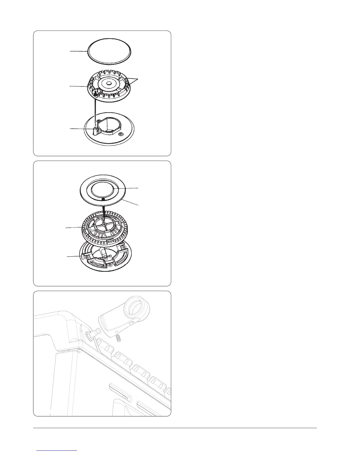
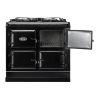
Connections). Ensure burner heads and burner caps
are correctly located (See Fig. 13.6 and Fig. 13.7), and
electrodes are not damaged.
3. Replace Module top plate as follows:-
D. Support top plate at front and reconnect the Earth and
wiring to the two neons.
E. Carefully lower the top plate into position taking care
not to damage wiring or neons.
F. Ensure holes for control spindles are aligned correctly,
and replace 2 screws into control panel.
G. Loosely screw the top plate down with 4 retaining
screws.
8. Verify that the two top plates are level and proceed with
tightening down.
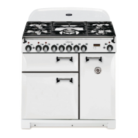
9. Fit the Module handrail bracket over the xing
stud located on the top plate. Lock into position by
tightening the grub screw nearest the appliance. (See
Fig. 13.8).
10. Next, t all thread stud into the insert located in the
one end of the Module handrail, then feed the handrail
through the bracket and screw the handrails together.
(See Fig. 13.9).
11. Once the handrail assembly is located squarely, lock the
handrail in position by winding in the grub screws on
the underside of each handrail bracket.
12. Once the handrails are locked in position, t the
handrail endcaps. The endcaps should be carefully
pushed into place until they sit ush with the outside
face of each bracket (a light smear of lubricant such as,
washing up liquid on the end cap ‘O’ rings may ease
tment.
DESN 511618
BURNER CAP
RETAINING
LUGS
DESN 511619
DESN 516855
Fig. 13.6
Fig. 13.7
Fig. 13.8
BURNER
CAP
BURNER
CAP
BURNER
RING
(WOK BURNER ONLY)
BURNER
HEAD
BURNER
HEAD
ELECTRODE
ELECTRODE