35
AGA Module Gas Hob - Freestanding / Integrated
DISCONNECT FROM ELECTRICITY SUPPLY BEFORE
SERVICING.
WHEN REWIRING ANY ELECTRICITY COMPONENTS
REFER TO CIRCUIT DIAGRAM AND FUNCTIONS
FLOW DIAGRAM ATTACHED BEFORE ELECTRICAL
RECONNECTION. CHECK THAT THE APPLIANCE IS
ELECTRICALLY SAFE.
NOTE: Turn o gas supply to the appliance before servicing
any gas carrying components. Always check appliance for gas
soundness after completion.
NOTE: Use soapy water solution to ensure there are no gas
leaks.
REMOVAL OF TOP PLATE
1. Disconnect from electricity supply and remove pan
supports and all control knobs.
A. AGA MODULE GAS HOB INTEGRATED ONLY
Remove the handrail page 32 from the module
top plate. Slacken grub screws and remove socket
screws from the jointing bracket to remove rail.
B. AGA MODULE GAS HOB INTEGRATED ONLY
Remove shroud (if tted) from rear of top plate.
C. AGA MODULE GAS HOB FREESTANDING AND
INTEGRATED MODULE Remove four chrome
buttons and the four top plate retaining screws (2
each side).
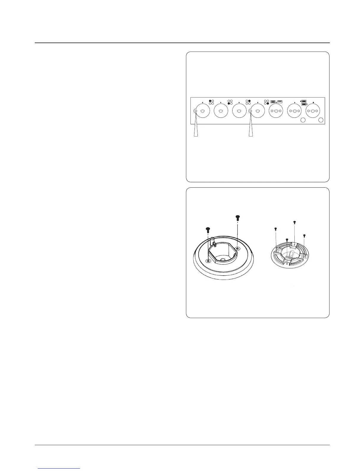
2. Remove left hand and centre shrouds from the control
panel to gain access to the xing screws. Remove two
screws from control panel (one from left hand hole and
one from centre hole) (Fig. 19.1).
3. Carefully pull top plate forwards slightly and lift up at
the front. Support top plate and disconnect the wiring
to the neons. Remove top plate.
4. Lay the top plate on its top face, suitably protected.
5. Re-assemble in reverse order.
19. Servicing notes
Fig. 19.1
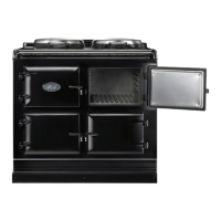
Fig. 19.2
DESN 517426
REMOVE 2 FIXING SCREWS
DESN 511646
(WOK BURNER ONLY)