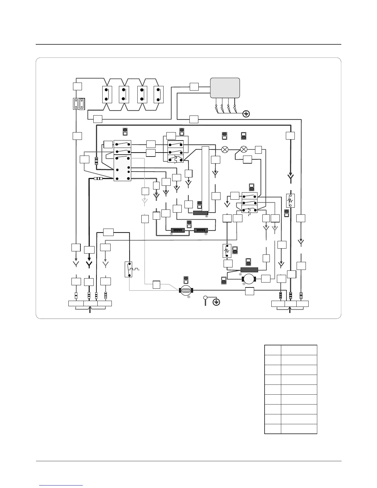
EasyManuals Logo

AGA DC5 User Manual

AGA DC5
48 pages
To Next Page IconTo Next Page
To Previous Page IconTo Previous Page
Page #37 background imageLoading...
Page #37 background image
33
MTB
N
N
N
3/12
4/12
4/12
6/12
6/12
9/12
12/12
8/12
10/12
5/12
7
/
12
2/12
B
A
Y
BR
BL
Y
BL
BL
BL
BL
BL
BL
BL
BL
BL
BL
V
V
R
Y
R
R
R
PK
BL
BL
BL
BL
4a
4a
4b
4
4
1
4
2
S1
P2
P1
S2
BK
BR
PK
BL
BR
A
A
A
D
E
F
G
H
I
K
L
N
M
O
P
P5
5
P6
6
1
2
1/12
GR
GR
11/12
BL
E
N
BR
C
BR
GR
BK
GR
BK
BR
L1 L2
L(A)
L3
GR
MTB
10/12
BL
BL
BL
BK
V
R
2
P6 6
5
P5
17. Circuit diagram
CAUTION: label all wires prior to disconnection when servicing controls wiring errors can cause improper and dangerous
operation. Verify proper operation after servicing.
A. Gas Tap Ignition Switch
B. Spark Generator
C. 2 Way Terminal Block
D. Grill Regulator
E. Top Oven Thermostat
F. Top Oven Neon
G. Bottom Oven Neon
H. Bottom Oven Thermostat
I. Top Oven Overheat Thermostat
J. Bottom Oven Heat Thermostat
K. Top Oven Element Thermal
Switch
L. Dual Grill Element
M. Bottom Oven Element
N. Bottom Oven Circulation Fan
O. Grill Cooling Fan
P. Grill Cooling Fan ‘Run On’ Thermal
Switch
MTB Master Terminal Block
DESN 517531
Code Colour
BR
Brown
BL
Blue
GR
Grey
BK
Black
Y
Yellow
V
Violet
PK
Pink
R
Red

Other manuals for AGA DC5

Questions and Answers:

Question and Answer IconNeed help?

Do you have a question about the AGA DC5 and is the answer not in the manual?

AGA DC5 Specifications

General IconGeneral
BrandAGA
ModelDC5
CategoryRanges
LanguageEnglish

Related product manuals