APPENDIX A
36 AGCO RoGator RG900/1100/1300 Hawkeye™ Installation Manual
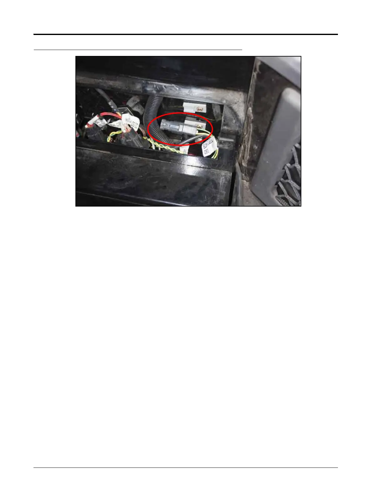
FIGURE 2. Upper Panel Right of the Operator Seat
4. Disconnect the ISO terminator from the 3-pin connector.
5. Plug in the ISOBUS adapter cable to the connectors to allow the ROS device to interface with the machine
ISOBUS and the Raven Hawkeye nozzle control system.
6. Plug the ISO terminator plug on to the second connector on the cable installed in Figure 5 on page 36.
7. Route the adapter cable to the back of the ROS device and connect to the receptacle labeled “5.”
8. To prevent issues with the Hawkeye Icon showing up on the C1000, perform the steps in AGCO Service Bulletin
Number 16-0104. This bulleting provides the steps to set the ISOBUS Terminal Generation to UT 2, turn the
ISOBUS Terminal Functions On, and assign the terminal number.
 Loading...