12
Installation and Commissioning
SET-UP DEVICE USING AGD TOUCH-SETUP
STEP 2 – SET ZONES CONTINUED
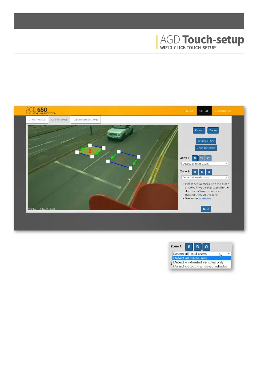
Detection Zones
Add the detection zones where required (using Zone 1 & Zone 2). The green arrows should follow the direction of
traic and be parallel with the road layout. Lane dierentiation can be achieved by placing zones in the middle
of each lane. A gap between each lane is required to stop false detections of adjacent lane traic.
Select the correct option from the drop-down list for your intended
application. Each zone operates independently.