6
AGD 650
DUAL ZONE STOP-LINE DETECTOR
AGD 650
DUAL ZONE STOP-LINE DETECTOR
AGD 650
DUAL ZONE STOP-LINE DETECTOR
AGD 650
DUAL ZONE STOP-LINE DETECTOR
Max 6m
Min 3m
Variable
adjustment
to suite all
applications
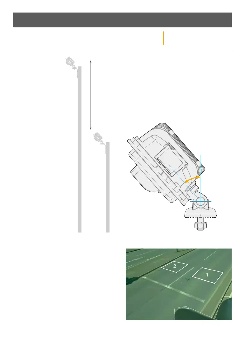
PHYSICAL INSTALLATION
STEP 1 - MOUNTING
HEIGHT – The AGD 650
Dual Zone Stop-line
Detector has excellent
performance when
mounted between heights
of 3-6 metres.
If you have an application
whereby you wish to
mount the detector outside
of these heights, then
please contact AGD.
STEP 2 - DETECTOR ALIGNMENT – The AGD650 Dual
Zone Stop-line Detector should be mounted using the
supplied hardware. The optimal mounting angle will
change depending on the installation location; aiming
the camera to the centre of the area of interest is a
good start position. The mounting angle may need
to be corrected during commissioning stage of the
installation. Ensure the detector is securely fixed and
the mounting nut is tight.
STEP 3 - FINAL ADJUSTMENT & VERIFICATION
Confirm the detector is correctly aligned, the entire
stop-line should be visible when looking at the
detectors view within the GUI. Where possible, the
field of view should include at least one full vehicle
length before and aer each detection zone. The
horizon should be out of view to reduce sun glare.
Once complete, please monitor traic to ensure zones
are correctly placed.
Installation and Commissioning