7
AGD 650
DUAL ZONE STOP-LINE DETECTOR
AGD 650
DUAL ZONE STOP-LINE DETECTOR
AGD 650
DUAL ZONE STOP-LINE DETECTOR
AGD 650
DUAL ZONE STOP-LINE DETECTOR
POWER UP SEQUENCE
Aer applying power to the unit, the red LED will illuminate for approx 30s while the operating system loads. The red
LED will then flash 5 times before going o. If detection zones have been set up the red LED will then come on when
either zone is in the detect state, otherwise it will remain o until the unit has been set-up and commissioned.
Upon power up, owing to the nature of the equipment power supply, an initial current of 15A <5ms can be drawn.
The supply should be fused as follows:
24/42V ac/dc - 3A circuit breaker or in-line fuse.
Opto-coupler ratings The voltage tolerances of supply
• Max current 60mA • 24/42V ac/dc ±20%
• Max Voltage 60V
• Max on-state impedance 25 Ohms
ELECTRICAL INSTALLATION
The detector is powered using a
24/42V ac/dc (±20%) supply. The power
is applied to the detector using the
multi-pin mating connector.
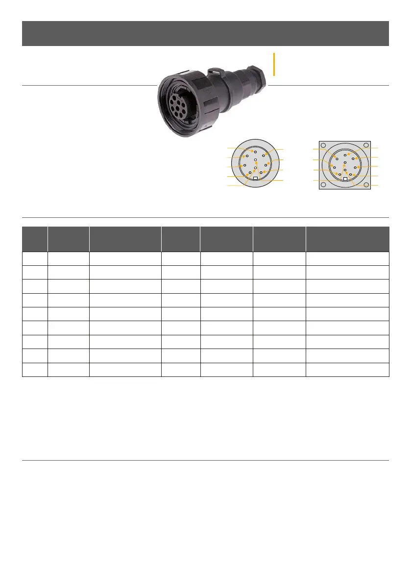
The AGD 650 Dual Zone Stop-line Detector is provided
with a Buccaneer Series PX0728/S 9 pole connector to
enable direct connection to the traic control system.
The pin-outs of the bulkhead connector are listed in
the table below:
CONNECTIONS
Installation and Commissioning
Pin
No.
Pin
Colour
Function Power
O
Power On
- No Detect
Power On
- Detect
Notes
1 RED +24V AC/DC - - - -
2 BLACK 0V AC/DC - - - -
3 GREEN Earth/Ground - - - Must be connected
4 WHITE Opto 1/2 Common - - - -
5 YELLOW Opto 1 N/O N/O N/C N/O Zone 1
6 BLUE Opto 1 N/C N/C N/O N/C Zone 1
7 - Not Connected - - - -
8 BROWN Opto 2 N/O N/O N/C N/O Zone 2
9 VIOLET Opto 2 N/C N/C N/O N/C Zone 2
n 1
n 7
Pin view of bulkhead
connector
Pin view of Bulgin
connector