5
AGD 650
DUAL ZONE STOP-LINE DETECTOR
AGD 650
DUAL ZONE STOP-LINE DETECTOR
AGD 650
DUAL ZONE STOP-LINE DETECTOR
AGD 650
DUAL ZONE STOP-LINE DETECTOR
1.4m or closer 1.5m and above
PHYSICAL INSTALLATION
The AGD650 requires specific installation parameters to allow the detector to operate correctly. Installing it
outside of these basic design parameters can reduce performance and detection accuracy so it’s important to
ensure you are within these parameters when installing the detector.
Distance from mounting pole to number of lanes covered
The pole’s location can restrict the number of lanes the 650 can be deployed on due to the detector’s field of view. The
table below depicts minimum recommended installation distances from the stop-line with a standard road layout.
Advance Stop-Line applications may vary: a long cycle refuge area may require a greater installation distance.
Minimum pole distance from stop-line (m) Number of lanes covered (3.4m lanes)
1.2 1
1.8 2
2.4
3
Choosing the correct mounting pole on dierent junctions
It’s important to mount the detector on the recommended pole to ensure high performance and reduce occlusion.
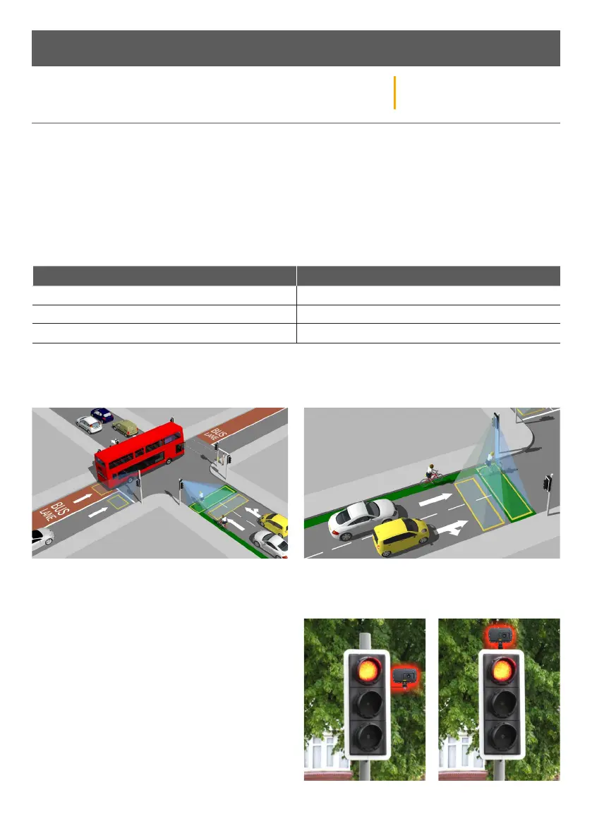
Mounting position in dierent environments
When installing the AGD650 on the traic head, please
use the 6” extension bracket supplied to allow it to see
over the backing boards and detect traic at the
stop-line. If the stop-line is 1.4m or less from the
mounting pole, then a 90º bracket looking around the
traic head is recommended.
Physical Installation - Parameters
Mount on the side of the road with the lowest number
of large vehicles (bus lanes/HGV routes)
Mount on the side of the road closest to approaching
cyclists for cycle refuge applications