DR 14s
1.
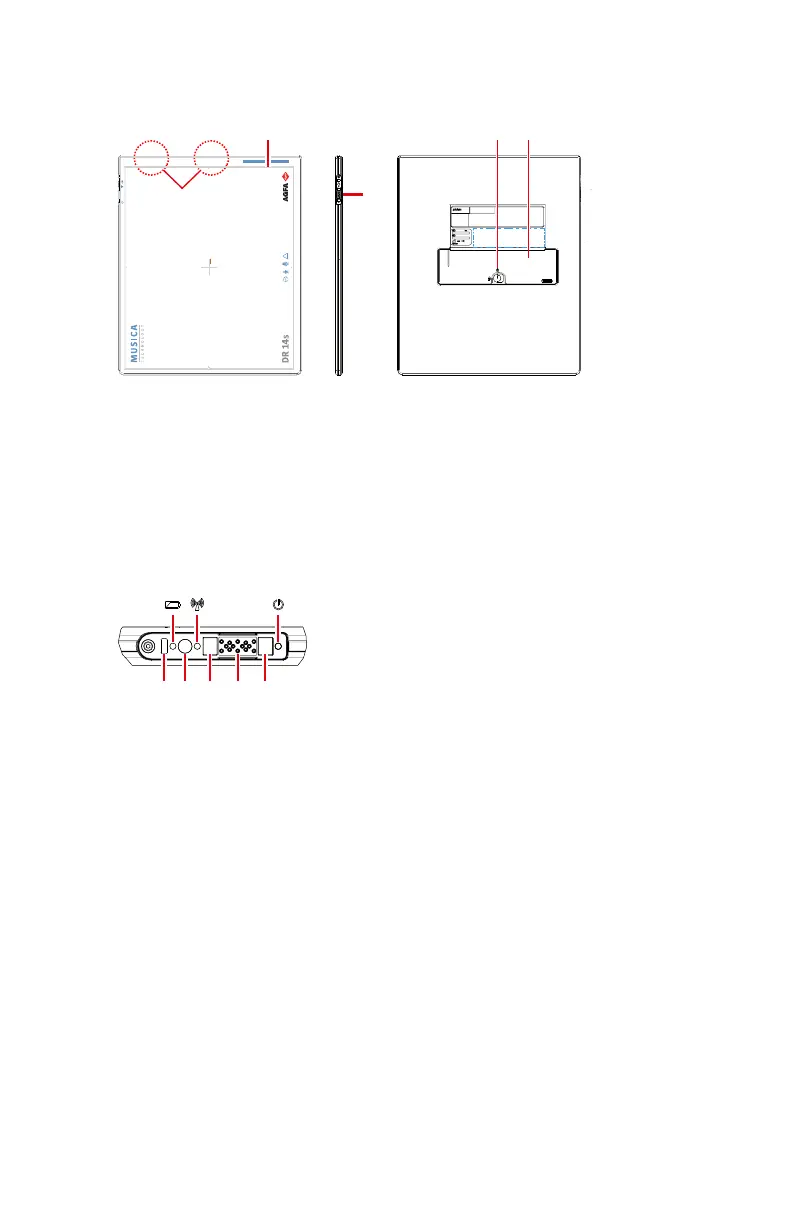
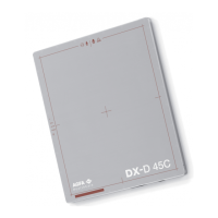
Effective imaging area border and center position indication
2.
Control panel
3.
DR Detector battery lock lever
4.
DR Detector battery
5.
Antenna of the wireless network adapter
Figure 4: DR Detector operation controls
1.
Battery indicator
2.
Wifi indicator
3.
Status indicator
4.
IR data port: communication port for the detector link (registration/
connection).
5.
On/off switch
6.
Magnets for DR Detector connector
7.
DR Detector cable connector
Figure 5: DR Detector control panel
Related Links
Detector Status Indicators on page 85
18 | DR 14s | Introduction to the DR Detector
0350B EN 20190319 1349 *