Diagrams 143
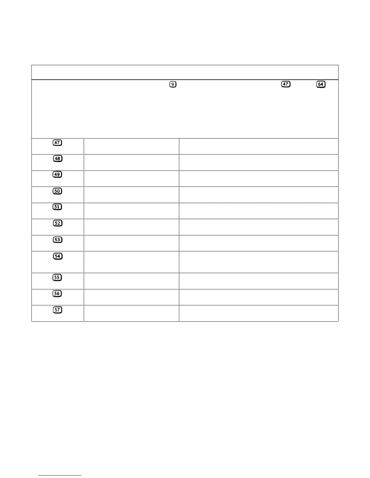
Table 6-3. Test Points (continued)
A4A1/A4A3 LEFT TUNNEL BOARDS (FIGURE 6-6)
Leave meter or scope common connected to test point when taking measurements at test points through .
The measurements were taken with full scale voltage and current programmed. The measurements were made first in the CV
mode with no load, and then in the CC mode with the load set for full scale voltage and current. Test points are listed for the
first regulator (closest to fan) and the last regulator stages only. The number of regulator stages that will be on (conducting)
depends upon the output current. In the CV mode with no load connected (no output current), only one or two stages will
be on conducting current through the down programmer stages. The remaining regulator stages will be off (not conducting).
In the CC mode with the load set for full scale output voltage and current all regulator stages will be on.
U201-3
OUTPUT CONTROL (comparator
+ input to all stages)
0 03V (6651-54), 0.06 (6655) in CV mode
0 6V in CC mode
U201-2
Stage 1 comparator -input 0.03V in CV mode
0.6V in CC mode
201-2
Stage 1 FET driver input 4V in CV mode
4.7V in CC mode
†Q202-3
Stage l reg control 0.6V m CV mode (reg Q201 on)
1.3V in CC mode (reg Q201 on)
U202-2
Stage 3 comparator -input 0.065V in CV mode
0.6V in CC mode
U202-1
Stage 3 FET driver control - 12 V in CV mode
4.4 V in CC mode
†Q208-3
Stage 3 reg control 0V in CV mode (reg Q207 off)
1.2V in CC mode (reg Q207 on)
U202-5
DP CONTROL 0.12V (6651-54), 0.24 (6655) in CV mode
2.4V (6651-54), 2.1 (6655) in CC mode
U202-6
DP stage comparator -input 0.12 V (6651-54), 0.24 (6655) in CV mode
2.2 V (6652-54), 0.26 V (6651), 0.3 V (6655) in CC mode
U202-7
DP stage comparator output -1.2V in CV mode
13.6V in CC mode
Q206-1
DP stage driver input -0.6V in CV mode
0.06 V (6652-54), 0.09 V (6651), 0.01 V (6655) in CC mode
 Loading...


