12 MAR 2000
Chapter 4
Diagnostics
Theory of operation
G2612A ALS Interface board
The ALS Interface board routes messages between the GC main board and the
components of the automatic liquid sampler system, and transmits power to the
injector(s) and the tray. Errors detected by the injector or the tray are routed to
this board, which then displays the error message on the 6890 GC or at the
ChemStation.
Power from the transformer enters the board at J5. This voltage is partially
rectified through half a diode bridge before being transmitted to the tray and the
injector(s) at approximately 33 VAC. The other half of the diode bridge resides
within the injector and the tray.
The ALS Interface board runs on +5 VDC from the main board through P5.
One fuse is located on this board at F1 to protect the transformer from
overvoltage.
6850 GC
The 6850 GC directly controls and powers the injector and tray. The power
circuitry is identical to that on the ALS interface board.
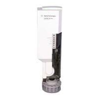
G2613A Injector
The G2613A Injector completes the rectification of power delivered by the ALS
Interface board (6890 only) or the 6850, and interprets all commands received
into the motions required to make an injection. Sensors and encoders are used
 Loading...
