Do you have a question about the Agilent Technologies 7100 and is the answer not in the manual?
Overview of the Agilent 7100 CE System and how to get started.
Information on how to access and use the online help system for assistance.
Guidance on locating specific information and tasks within the manual and online help.
Details on available learning resources and documentation for the CE system.
Information on environmental and physical requirements for instrument installation.
Details on power supply capabilities, voltage, and safe power connection practices.
Information regarding the types of power cords supplied and their proper use.
Requirements for instrument placement, including space for air circulation and connections.
Specifications for ambient temperature and humidity for optimal instrument operation.
Technical specifications detailing the instrument's physical characteristics and dimensions.
Details on the instrument's performance capabilities and features.
Step-by-step instructions for safely unpacking the Agilent CE instrument.
Procedure to follow if the instrument packaging shows signs of external damage.
Initial steps and options for connecting the CE instrument to a LAN.
Details on configuring the necessary TCP/IP network parameters for LAN connection.
Information on using the physical configuration switch for LAN setup.
Options for selecting the instrument's initialization mode for network connection.
Manual settings for LAN link speed and duplex mode.
Procedure to save network configuration parameters using the Bootp service.
Steps for manually configuring network settings via Telnet or other methods.
Explanation of the Agilent Bootp Service for IP address administration.
How to find the instrument's unique MAC address for network identification.
Overview of the system components: CE instrument, ChemStation, and Lab Advisor software.
Guidance on the procedures for starting up and operating the Agilent CE instrument.
Step-by-step instructions for powering on and initializing the CE instrument.
Procedure for starting the computer and the ChemStation software.
Initial setup steps for ChemStation software, including configuration.
Explanation of the CE diagram interface for monitoring instrument components.
Description of the functions available on the ChemStation software toolbar.
Detailed explanation of the CE diagram components and their icons.
Accessing instrument control and method parameters via context menus.
Performing immediate actions on instrument components through the CE diagram.
Storing parameters to ensure controlled shutdown during errors.
Command to locate the instrument using its status indicator LED.
Using the vialtable for managing vials and checking method/sequence consistency.
Tasks required to prepare the CE instrument for running an analysis.
Introduction to running applications in CE mode and its suitability.
Description of method parameters for data acquisition and analysis.
Programming methods to use specific vials for inlet or outlet home positions.
Setting and controlling the temperature of the capillary cassette.
Controlling parameters of the power supply, including voltage, current, and power.
Setting voltage, current, and power values as limits for the system.
Setting a lower limit for current to warn of system instability.
Defining separation time and post-analysis equilibration time.
Managing buffer composition by automatically refilling buffer vials.
Steps to condition capillaries for stable analysis conditions.
Using a command to empty space between capillary and electrode to prevent carry-over.
Choices for CE injection techniques: hydrodynamic, electrokinetic, or program.
Procedure for sample injection using pressure or vacuum.
Procedure for sample injection using applied voltage, current, or power.
Comparison of hydrodynamic and electrokinetic injection methods.
Advanced injection tasks using the injection table and timetable.
Programming parameters at specific times during the run.
Monitoring and storing CE-specific raw data like leak current and pressure.
Setting parameters for the detector, including signals, wavelengths, and peak width.
Defining detector signals, their wavelengths, and bandwidths.
Setting the optimum response time for the detector based on peak widths.
Defining points for taking and saving spectra during analysis.
Defining special stoptime and posttime for the detector.
Setting up the zero offset and attenuation of the analog output signal.
Setting a margin for peaks with negative absorbance.
Zeroing the baseline of the detector before or after an analysis.
Option to save lamp life by deselecting lamp use if a different detector is configured.
Programming detector parameters like wavelength and peak width over time.
General guidance for solving common instrument failures and issues.
Troubleshooting steps for when the instrument fails to power on.
Information about the leak sensor and actions to take if a leak is detected.
Troubleshooting steps for a blocked replenishment needle due to buffer precipitation.
Understanding and troubleshooting leakage current issues in the instrument.
Identifying and resolving issues related to a broken capillary.
Troubleshooting leakage current caused by contamination of the insulation plate.
Checking if an injection vial is filled when encountering issues.
Instructions for cleaning vials to prevent contamination.
Addressing air bubbles in sample or buffer vials that can cause injection issues.
Troubleshooting air bubbles within the capillary that affect electropherograms.
Resolving issues related to foam formation in SDS buffers within the replenishment system.
Overview of the Agilent Lab Advisor software for diagnostics and maintenance.
Steps for configuring the Lab Advisor software to communicate with the CE instrument.
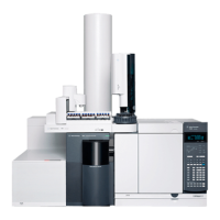
Identification of the main physical components of the Agilent CE instrument.
Detailed information about the instrument's electronic components and connectors.
Information on fuse types, locations, and replacement procedures.
Description of the instrument's firmware structure (resident and main systems).
Procedure for updating the instrument's firmware using software tools.
Information on controlling the Diode Array Detector and its parameters.
Using the DAD control dialog in ChemStation to manage the UV lamp and analog output.
Step-by-step guide for replacing fuses in the instrument's power supplies.
Procedure for installing drainage tubing to collect instrument condensation.
Information on connecting and using an external water bath for sample tray cooling.
Explanation of the built-in AD converter for analog signal processing.
General SOPs for regular maintenance tasks on the Agilent CE instrument.
Summary of maintenance procedures, typical frequencies, and important notes.
Procedure for cleaning electrodes, pre-punchers, and the insulation plate regularly.
Steps to prepare the instrument before performing maintenance tasks.
Instructions for safely removing the instrument covers to access internal components.
Procedure for accessing the instrument's electrodes for cleaning or inspection.
Steps to access the liquid handling module for maintenance or inspection.
Procedure for accessing and removing the pre-puncher components.
Detailed steps for cleaning the instrument's electrodes.
Detailed steps for cleaning the instrument's pre-punchers.
Detailed steps for cleaning the instrument's insulation plate.
Procedure for correctly reinstalling the pre-punchers after cleaning.
Steps for reinstalling the electrodes and insulation plate after maintenance.
Instructions for reinstalling the capillary cassette into the instrument.
Procedure for reinstalling the instrument's front cover.
Procedures for maintaining the buffer replenishment system.
Steps for changing the buffer solution in the replenishment system.
Procedure for flushing and storing the replenishment system when not in use.
Troubleshooting steps if the instrument fails to build pressure or vacuum.
Starting replenishment maintenance operations via software.
Operation to flush cleaning solutions through the replenishment tubing.
Operation to replace liquid in tubing and fill/empty vials for cleaning.
Function to dissolve buffer crystals and clean the level sensing needle.
Procedure for replacing the air inlet filter for the instrument's air pump.
Location and replacement of the air inlet filter.
Procedure for replacing the deuterium lamp in the instrument.
Steps for safely removing the old deuterium lamp.
Procedure for installing a new deuterium lamp.
Guidelines for cleaning the exterior of the instrument case.
List of parts and materials required for instrument maintenance.
General safety precautions to be observed during all phases of instrument use.
Procedure for setting up and running a test sample for instrument verification.
Safety procedures for handling toxic, hazardous, or biological samples and solvents.
Information regarding the WEEE Directive for proper disposal of electronic waste.
Guidelines on using appropriate cables to ensure EMC compliance.
Manufacturer's declaration regarding the product's sound pressure emission levels.
Information regarding the limited right to use the instrument and patented technologies.
Information on accessing Agilent's website for product and service updates.
| Brand | Agilent Technologies |
|---|---|
| Model | 7100 |
| Category | Laboratory Equipment |
| Language | English |