86 Agilent 7100 Capillary Electrophoresis System User Manual
5 Using the Agilent 7100 Capillary Electrophoresis System
Working with the CE Diagram
Graphical User Interface Explanation
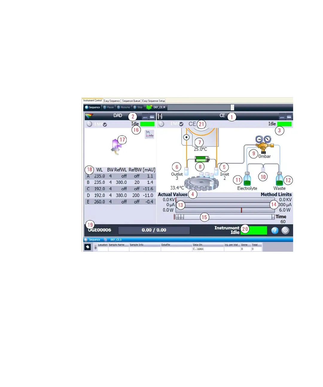
Components of the Agilent CE instrument in the CE diagram (synonym
dashboard) are shown in Figure 17. Each component in the instrument is
represented by an icon in the CE diagram or DAD diagram.
Figure 17 The CE and DAD diagram represents each component in the instrument
1 CE control diagram 8 High voltage power supply 15 Method steps and progress
2 DAD control diagram 9 Internal pressure 16 DAD status
3 CE status 10 Replenishment station 17 Lamp
4 Tray / tray temperature 11 Electrolyte bottle / pressure storage 18 Detector wavelengths/spectra
5 Inlet lift / loaded vial 12 Waste bottle / vacuum storage 19 Instrument identifier
6 Outlet lift / loaded vial 13 Current electrical values 20 Overall instrument status
7 Cassette temperature 14 Electrical parameter from method 21 Instrument mode