Chapter 4 243
Troubleshooting the Analyzer
Using the Internal Service-Diagnostic Routines
Verify the FM coil driver
It is only necessary to perform this service-diagnostic routine if the
failure appears in narrow spans (10 MHz and below).
1. Set the analyzer span to 10 MHz.
Be sure to set the span before performing the service-diagnostic
routine. For example, if the span is not set first, the trace will appear
at the top of the display instead of the expected ramp.
2. Return to the diagnostics menu by pressing the following analyzer
keys.
CAL, More 1 of 4, More 2 of 4
SERV DIAG, More 1
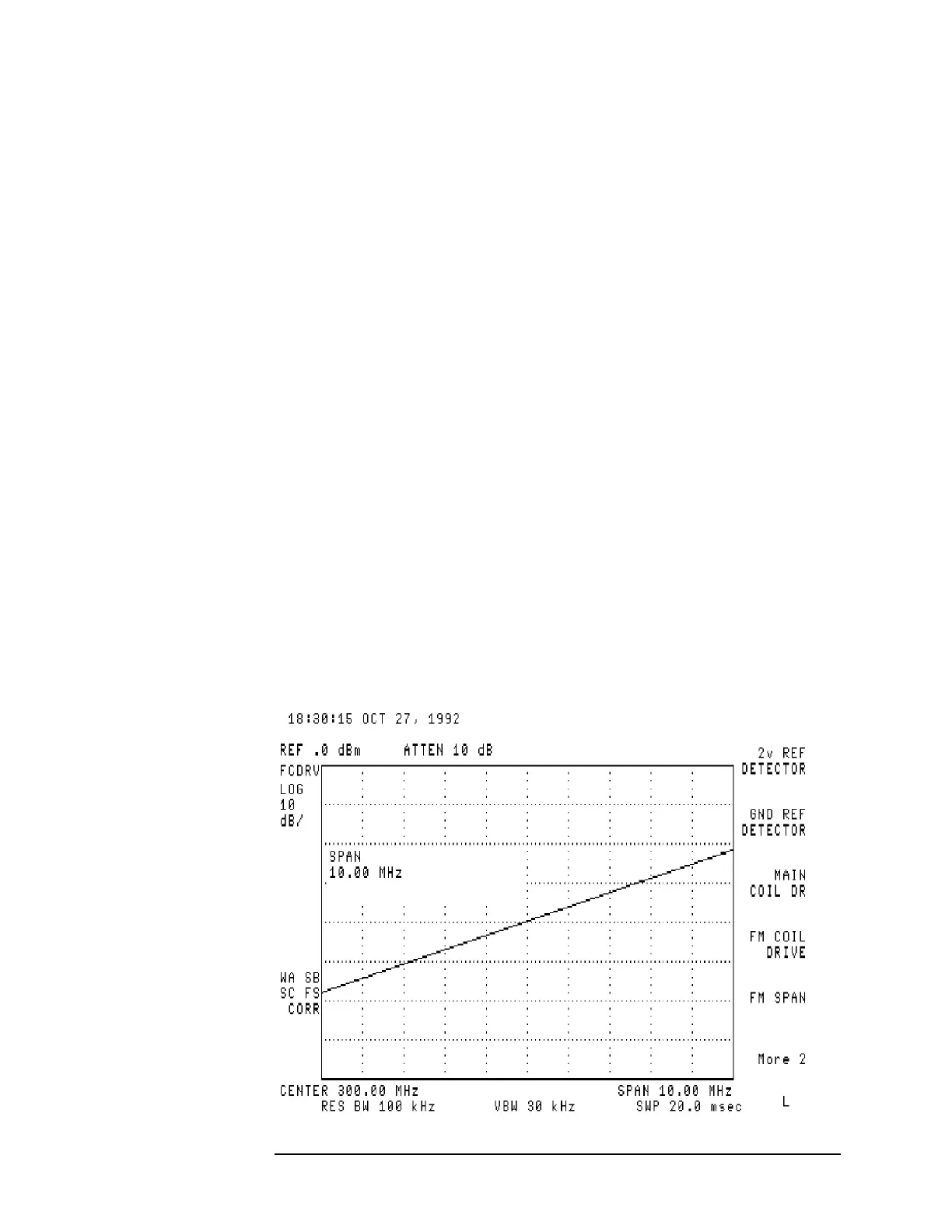
3. Verify the FM coil driver by pressing FM COIL DRIVE.
• If the signal trace is similar to Figure 4-10, the FM coil driver is
functioning properly.
• If the signal is not similar, suspect the A7 analog interface board
assembly.
• For analyzers equipped with an A25 counterlock assembly only: If
all other service-diagnostic routines operate properly, disconnect
the A25 counterlock assembly, perform the FREQ CAL
calibration routine, then operate the analyzer as an unlock
instrument.
If the analyzer is corrected, suspect the A25 counterlock
assembly.
Figure 4-10 FM Coil Driver with ≤ 10 MHz Span
 Loading...

