3.4. Backplane
3.4.1. Backplane Specifications
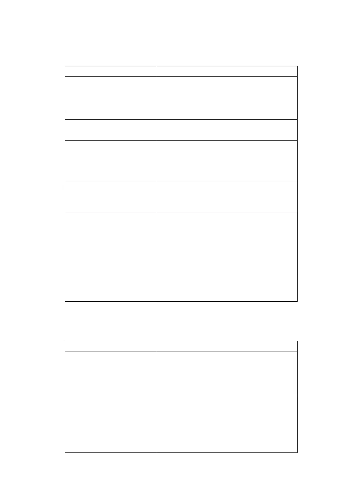
Conformity PICMG 2.0 R2.1
Size
Height 3U: P1 and P2 connectors (32/64 bit).
CC103: 3 slots
CC105: 5 slots
CC108: 8 slots
System Slot Left side (bottom)
GND (Common Return Outputs)
Floating. Connected to Chassis Ground with an
100kOhm resistor in parallel with >60nF capacitor.
V(I/O) Voltage and Coding Keys
Important:
V(I/O) should not be modified
without changing the coding keys
V(I/O): internal switch selectable
Standard: position 5, connected to +5V with 5V
brilliant blue coding key assembled
On request: position 3.3, connected to 3.3V with 3.3V
cadmium yellow coding key assembled
Material FR4: UL 94V0 recognized
Connectors P1 (Module A) and P2
(Module B)
Conforms to IEC917 and IEC 1076-4-101.
UL 94V0 rated.
Working Currents
1.5A@25°C max per contact (1.2A@50°C).
Power supply contacts per slot, connectors P1 and P2:
+3.3V: P1; 10 contacts
+5V: P1; 8 contacts
+12V: P1; 1 contact
−12V: P1; 1 contact
V(I/O): P1; 5 contacts P2; 6 contacts
GND: P1; 14 contacts P2; 18 contacts
Bus Frequency
(66 MHz operation is supported for
the 3 and 5 slot versions ONLY)
Internal switch selectable:
Position 33: 33 MHz only (M66EN grounded)
Position 66: 33 MHz or 66 MHz (M66EN open)
3.4.2. Power Supply Status
The Derating (DEG#) and Supply Fail (FAL#) are implemented only for the System Slot.
Levels TTL (0 = <0.8V, 1 = >2V)
DEG#
Mains AC accurate signal
Indicate that the power supply is beginning to derate its
power outputs.
1 = Mains AC is accurate.
0 to 1: 400msec minimum before FAL#.
1 to 0: 20msec minimum before FAL# and DC outputs
shutdown.
FAL#
Global DC outputs accurate signal
Indicate that an DC output from the power supply has a
failure.
1 = All DC outputs are accurate.
0 to 1: 20msec minimum after the DC outputs are
accurate.
1 to 0: 4msec maximum after the start of the DC output
shutdown.
User Manual: Agilent Acqiris 3-, 5-, and 8-slot cPCI Crates Page 16 of 28