Appendix Service Information
Measurement Techniques
181
Service
Information
Measurement Techniques
Setup for Most Tests
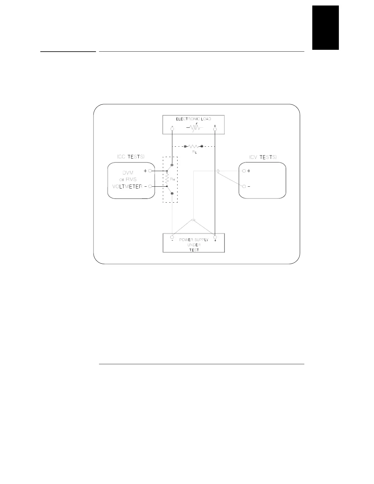
Most tests are performed at the front terminals as shown in Figure A-1. Measure the
dc voltage directly at the (+) and (-) terminals on the front panel.
Figure A-1 Performance Verification Test Setup
Current-Monitoring Resistor
To eliminate output current measurement error caused by the voltage drops in the
leads and connections, connect the current monitoring resistor between the (-) output
terminal and the load as a four-terminal device. Connect the current-monitoring leads
inside the load-lead connections directly at the monitoring points on the resistor
element (see R
M
in Figure A-1).