Chapter 2 49
Overall Troubleshooting
Troubleshooting Using Auto-Align Tests
Troubleshooting Using Auto-Align Tests
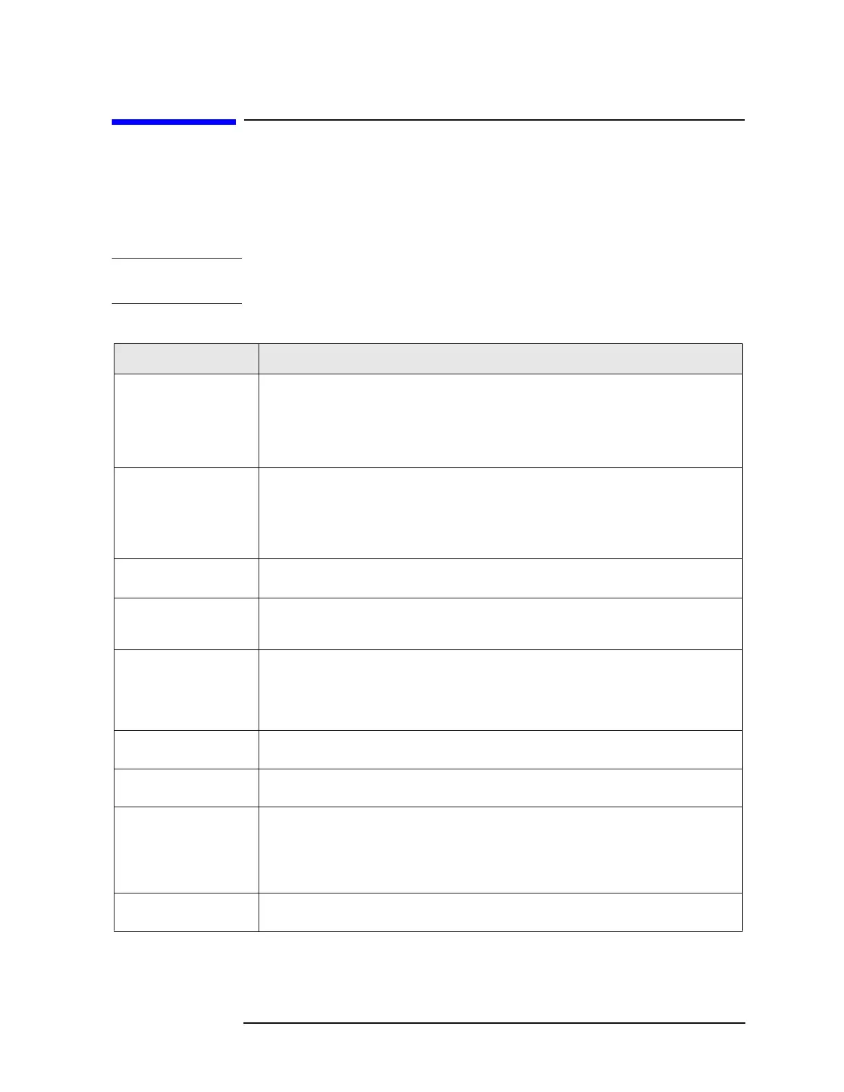
A sequence of alignments occur automatically when the analyzer is
powered on. A “pop-up” box will appear on the display indicating which
alignment is being performed. In the table below, you will find a
description of each auto-alignment.
NOTE The auto-alignment process can be aborted at any time by pressing the
ESCAPE key.
Table 2-2 Sequence for Auto-Align Procedures
Procedure Name Procedure Description
Align 2
nd
LO Locks the phase lock loop that maintains the 2
nd
LO, 3.6 GHz oscillator on the A9 2
nd
LO
assembly. This allows the 2
nd
LO to phase lock to the 600 MHz reference oscillator on the
A11 Reference assembly, improving the system phase noise.
Must drive the ADC reading on the 2
nd
LO to 180-220 counts. This corresponds to an error
voltage of 0.5 to 0.6 volts.
Align LO This alignment adjusts the Pretune Dac to minimize loop voltage error, and calculates the
optimal Pretune DAC slope and intercept values. The values are then stored in calibration
files.
Must be able to minimize loop error voltage at two different frequencies with a DAC setting
between 10 and 4050.
Align 2
nd
LO Pwr
Finds the DAC setting that gives an ADC reading that is equal to the ADC value written
during the manufacturing process.
Rough Cal Gains This alignment does a rough/preliminary setup of AIF main gain and RF gain to allow other
alignments to function before the completion of Align AIF Main Gain and Align RF Gain.
An absolute gain level is set.
Trigger Interpolator The trigger interpolator provides a way to measure trigger timing to a fine precision. A
unique trigger is used, which has timing that can be varied relative to the sample clock
using an 8-bit control DAC on the A8 Analog IF. If it is not monotonic, or the expected
variation is not verified, this alignment will FAIL. The A7 Digital IF assembly could be
faulty also since it receives trigger inputs.
ADC Offset DAC’s Offset DAC’s for each of the 4 ADC range positions on the A7 Digital IF assembly are
aligned to reduce the overall DC offset.
ADC Dither CF The ADC dither needs to be centered to prevent its own harmonics from folding back into
the center of the IF passband. This routine adjusts the dither DAC on the A7 Digital IF.
ADC RAM Gains Each of the 4 ADC range positions has its own page of RAM memory. This is a mapping of
ADC bits to “output” Data bits. This RAM memory is on the A7 Digital IF assembly.
This alignment uses the 50 MHz CW calibrator signal to measure the relative response of
each range page. The RF input attenuator and analog IF main gain DAC are dynamically
adjusted to help keep the actual ADC signal level approximately the same.
IF Image Filter The 321 MHz calibrator oscillator is used to align the 5 DAC’s of the image filter on the A10
3rd Converter assembly.
 Loading...


