Chapter 4 153
Downloading and Using Files
Downloading ARB Waveform Data
Downloading ARB Waveform Data
The signal generator accepts I/Q waveform data downloads. User-defined I/Q waveforms can be sequenced
together with other waveforms and played as part of a waveform sequence (see the User’s Guide for details
on sequencing waveforms).
The signal generator uses a two-file format when generating waveform data: an I/Q waveform file, and a
marker file. If you do not create a marker file for the I/Q waveform file, the signal generator automatically
creates one. This automatically generated default marker file comprises all zeros. The marker data drives the
signal generator’s rear-panel EVENT output connectors:
• Marker bit 1 drives EVENT 1 (BNC)
• Marker bit 2 drives EVENT 2 (BNC)
• Marker bit 3 drives EVENT 3 (Auxiliary D-Connector, pin 19)
• Marker bit 4 drives EVENT 4 (Auxiliary D-Connector, pin 18)
The I/Q waveform data usually drives the I and Q ports of the I/Q modulator. The waveform data is
described using 16-bit I and 16-bit Q integer values in 2’s signed complement format. The I and Q data
values are interleaved, creating a single I/Q waveform data file.
The marker file comprises 8-bit bytes, each of which has four marker bits and four unused bits. The result is
that the I/Q file has four times as many bytes as the marker file.
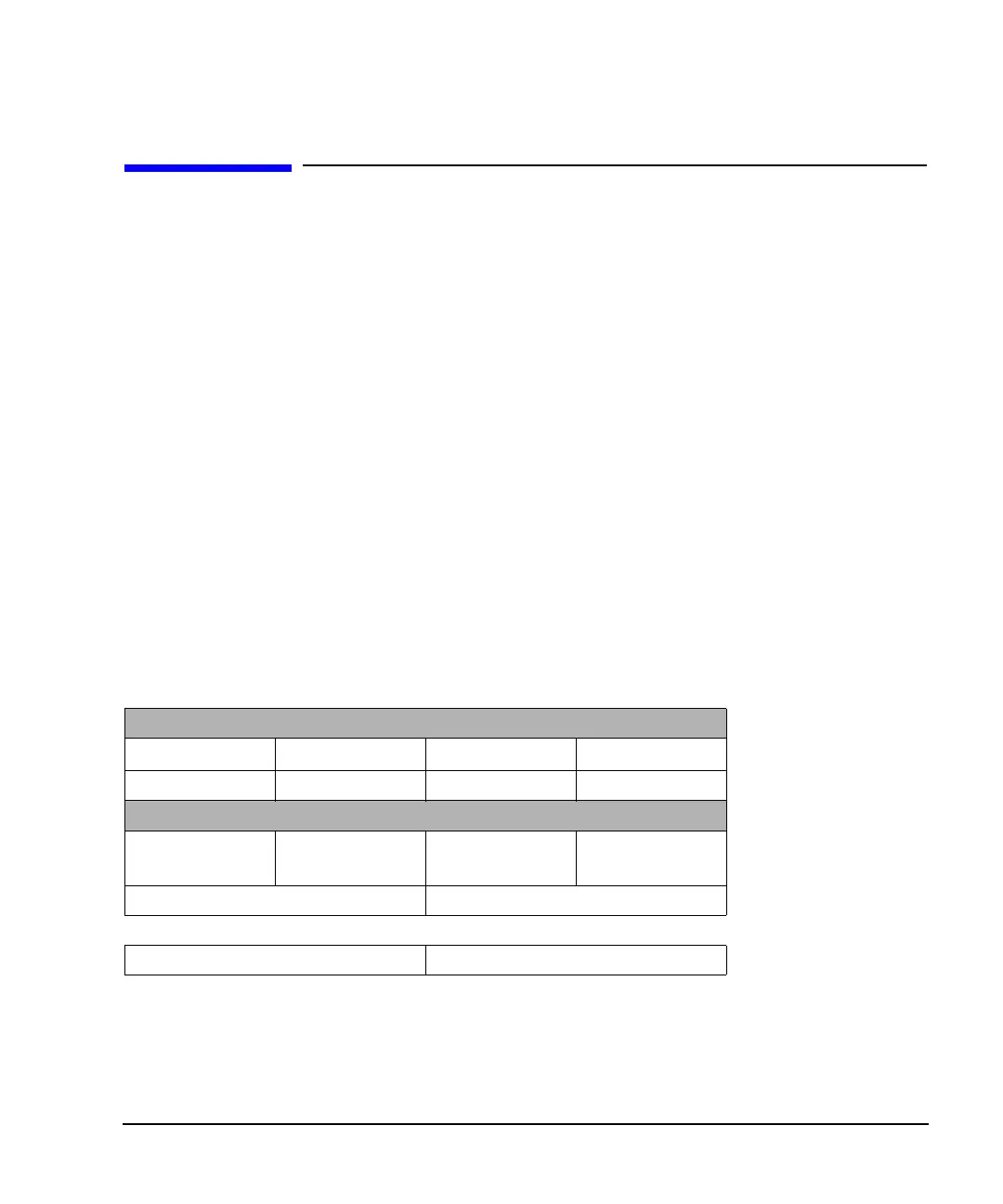
The 2-byte I integer and 2-byte Q integer values, along with a marker byte make up one sample, and one
point is one pair of I/Q values. There are five bytes of data for every sample as shown in the following table.
Marker File Location
MKR1: /user/bbg1/markers/ NVMKR: /user/markers/
I/Q Data File Structure
I
o
= 16 bits Q
0
= 16 bits I
1
= 16 bits Q
1
= 16 bits
2 bytes 2 bytes 2 bytes 2 bytes
Marker File Structure
4 bits unused
MSB
M
0
= 4 bits
LSB
4 bits unused
MSB
M
1
= 4 bits
LSB
1 byte 1 byte
1 sample 1 sample
 Loading...


