16 Instructions for Use
274/342 TwisTorr 74 FS User Manual / 87-901-053-01
Pump Fixing
WARNING!
Failure to comply with these installation instructions could result in the pump
detaching from the system in the event of a rotor failure, which could cause
property damage or serious injury or death.
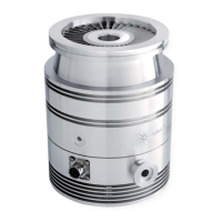
The TwisTorr 74 FS can be installed in any position. Fix the TwisTorr
74 FS in a stable position, mounting the inlet flange of the turbopump
to the system counter-flange, with a connection capable of
withstanding a torque of 250 Nm around its axis.
The following table shows, for each flange, the necessary number of
clamps and the relevant fixing torque.
FLANGE FIXING DEVICE N. FIXING TORQUE
ISO 63 K M10 clamps: IC63250DCMZ 4 22 Nm
CFF 4 ½ Mounting Kit X3502-68007
Metric screws X3502-68008
American screws X3502-
68009
8 20 Nm
CFF 2 ¾ Screws 6 20 Nm
KF 40 Clamp KF40 1 -
The turbopump with ConFlat inlet flange must be fixed to the
vacuum chamber by means of the appropriate Agilent hardware. See
the appendix "Technical Information" for a detailed description.
NOTE
The TwisTorr 74 FS cannot be fixed by means of its base.
 Loading...