Edition 11.98 Power Hoe 6000 17
3. Devices and Operating Elements
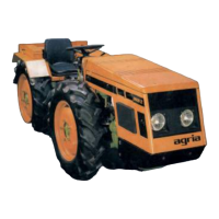
1 Locking pin
2 R-clip
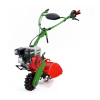
1 Coupling unit
2 Adapter tube
3 Locking pin
4 R-clip
5 Crank
Gearbox
The power hoe has a 3-speed manual
gearbox that drives the wheels and the
tiller.
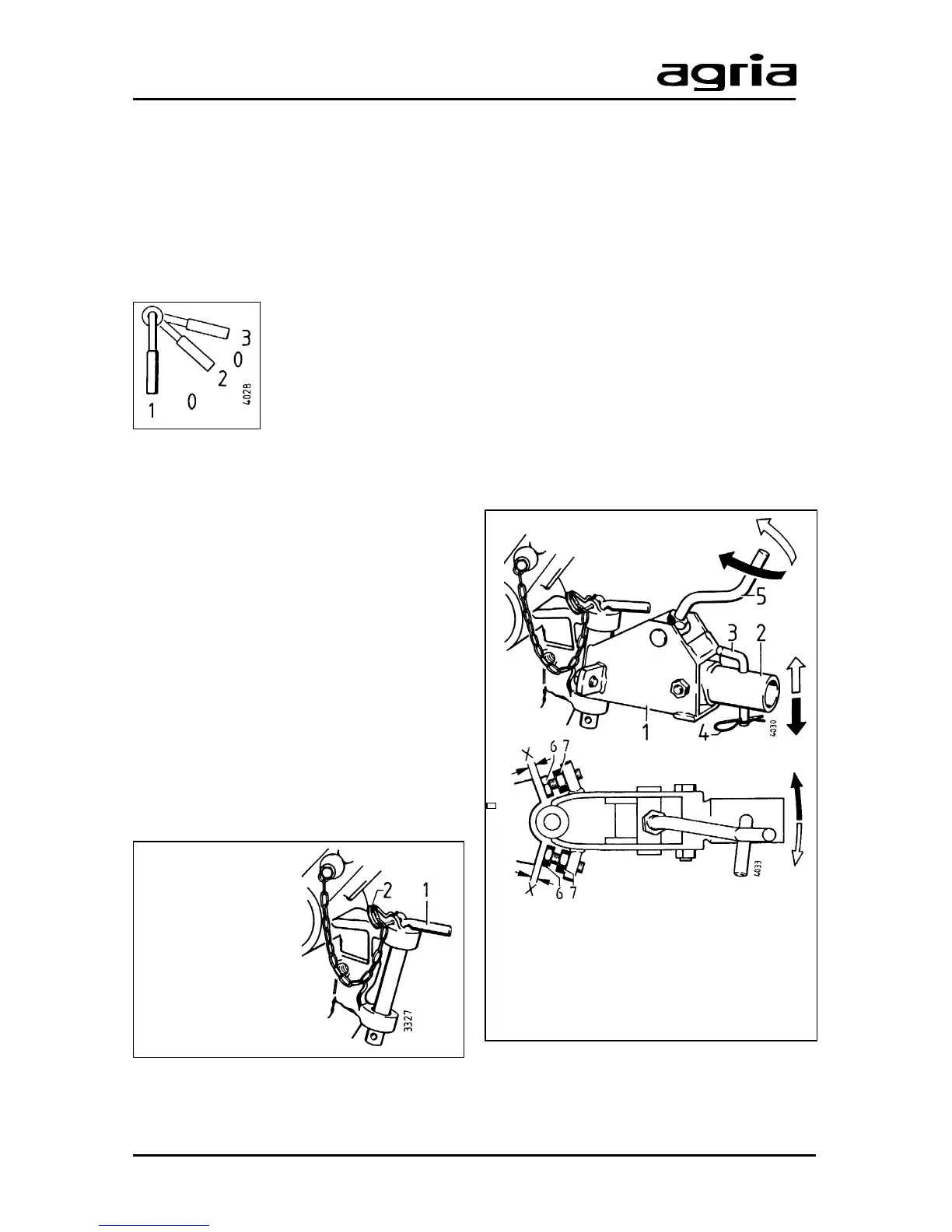
Speed steps
Lever (C/3) shifts the
gears on wheel-drive
and hoeing-drive:
I .............................................. 1st gear
II ............................................ 2nd gear
III ............................................ 3rd gear
0 ................................................neutral
A roller chain transmits power to the shaft
that drives the wheels and the hoeing unit.
I
Only change gears when clutch
is decoupled. Move shift lever
only with your hand.
Hitch
Trailed implements, for example leg and
plough, are pin-attached (1) to the hitch
(A/18).
Ensure the pin is locked in place with the
R-clip (2) after the implement is attached.
Coupling Unit
The coupling unit (1) is an adapter that
serves as a link between the hitch and
the mounted attachments (plough, culti-
vator and combined rotary harrow).
These attachments have a coupling pin
that is inserted into the adapter tube (2).
Attach the pin (3) with the locking pin and
lock with R-clip (4).
The crank (5) on the coupling device
allows setting individual working depths.
Set the travel ”X” with the stop bolts 6
and 7 to adjust the hoe's steering when
an attachment is mounted.