Home
Airspan
Wireless Access Point
AirSpeed 2900
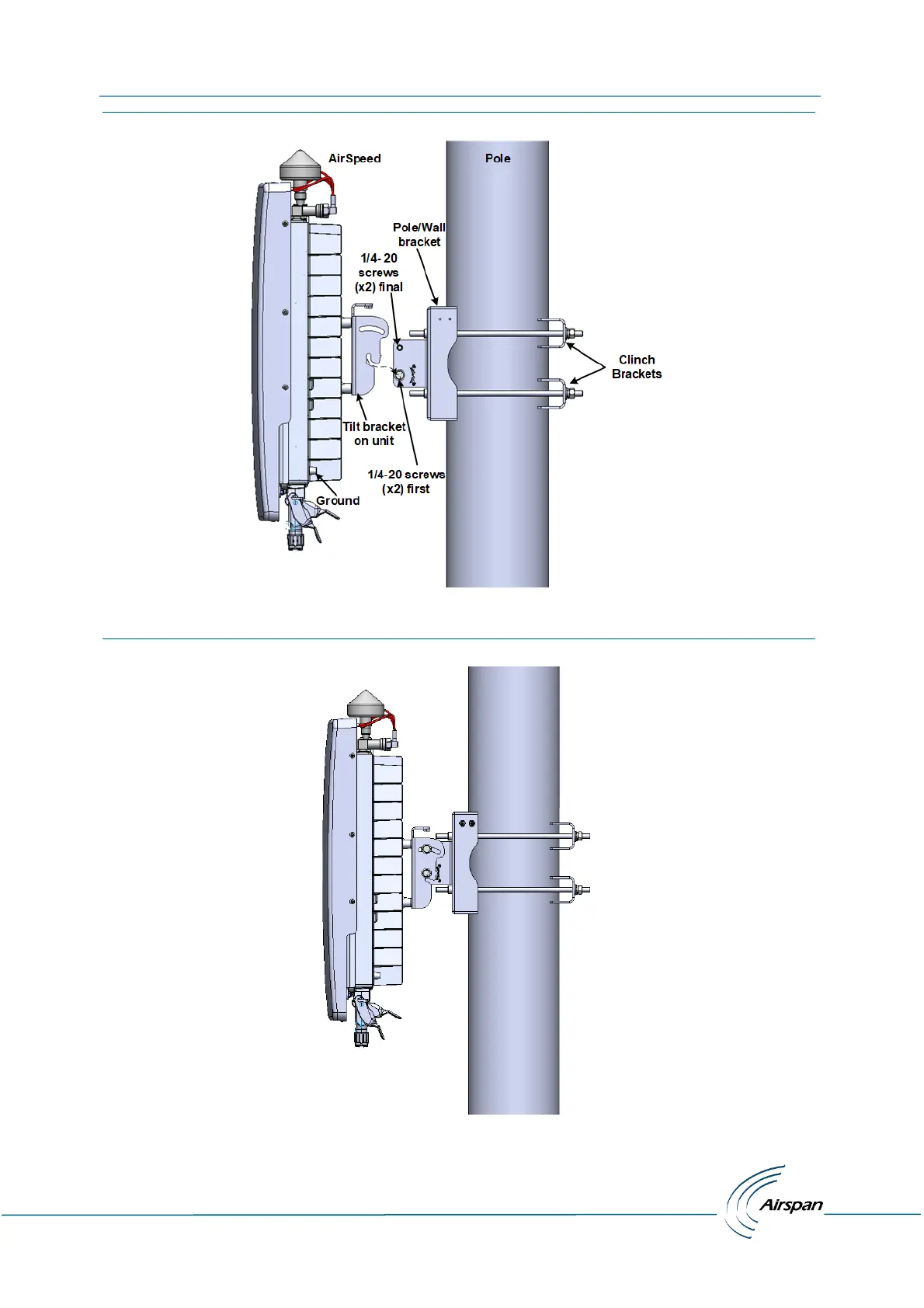
Page 27 (Figure 8: Pole Mounting Assembly)
Airspan AirSpeed 2900 - Figure 8: Pole Mounting Assembly; Figure 9: Mounted on Pole
37 pages
Manual
Save Page as PDF
To Next Page
To Next Page
To Previous Page
To Previous Page
Loading...
AirSpeed 29
00 gNB 5
G OD Installation Gu
ide
© Copyr
ight
Airsp
a
n
Networks
Ltd.,
2021
P/N D
UG0108
5
Rev.
A,
Nov 202
1
25
F
i
g
u
r
e
8
:
P
o
l
e
M
o
u
nt
i
n
g
A
s
s
e
m
b
l
y
The fo
llowi
ng disp
l
ays th
e Ai
rSpeed
2900
mounted
on a pole.
F
i
g
u
r
e
9
:
Mo
un
t
e
d
o
n
P
o
l
e
26
28
Table of Contents
Main Page
Default Chapter
3
Table of Contents
3
Document Information
6
Revision History
6
Warnings and Cautions
7
Human Exposure to Radio Frequencies
7
Radio Interference
7
Modifications
7
General
8
Important Safety Instructions
8
Safety
9
Warning of Hazardous Voltages
9
Adherence to European Directive 2014/53/EU
9
Warning Symbols
10
Service Information
10
UL Information
10
Lightning Protection
10
Outdoor Ethernet Cabling
11
Declaration of Conformity
11
GPS Compliance
14
Maximum Output TX Total Power
14
Voltage and Amperage
14
Table 1: Airspeed 2900 Gnb Maximum Output TX Total Power
14
Table 2: Voltage & Amperage Draws
14
Antenna System
15
Integrated Antenna Parameters
15
Table 3: Integrated Antenna Parameters
15
About this Document
16
Purpose
16
Intended Audience
16
Document Conventions
16
Table 4: Typographic Conventions
16
Related Reading
17
Customer Care Help Desk
17
Airspan Encourages Comments
17
1 Getting Started
18
Airspeed 2900 Installation Checklist
18
Figure 1: Airspeed 2900 with GPS Attached
18
2 Verifying Prerequisites
19
Verifying Site Requirements
19
Verify Installation Requirements
19
Verify the Tools
19
Table 5. Minimum Hardware Requirements
19
Verify the Parts and Kits
20
Table 6. Parts & Kits
20
Power Supply
21
Connections
21
Figure 2: Airspeed 2900 Top Ports (with Integrated Antenna)
21
Figure 3: Airspeed 2900 Bottom Ports
22
Physical Dimensions
23
Environmental
23
Figure 4: Environmental and Standard Compliance
23
Table 7. Airspeed 2900 Physical Dimensions
23
3 Airspeed 2900 Installation
24
Connecting the GPS Antenna
24
Weather-Proofing the GPS Antenna Connection
24
Tilt Bracket Assembly
24
Pole Mounting Assembly
25
Figure 5: Tilt Bracket Assembly
25
Figure 6: Position on Pole
26
Figure 7: Mounting Bracket on Pole
26
Figure 8: Pole Mounting Assembly
27
Figure 9: Mounted on Pole
27
Wall Mount Assembly
28
Figure 10: Airspeed on Wall
28
Tilt Adjustment
29
Figure 11: Tilt Adjustment
29
4 Connect and Manage Cables
30
Grounding
30
Figure 12: Ground Connection
30
LED Display
31
Table 8: System LED Function
31
Single Mode LC Cable Insertion
32
DC Cable Preparation
32
Figure 13: Pre-Assembled Single Mode LC Cable
32
Figure 14: Stripping Dimensions (DC Cable)
33
Figure 15: Open Housing Lock
33
Figure 16: Separate into Sections
33
Figure 17: Insert Gland Nut
33
Figure 18: Pass DC Cable Thru
33
Figure 19: Power Wire Connection
34
Figure 20: Tightening of Set Screws
34
Figure 21: Tighten the Strap Clamp
34
Figure 22: Align Marks + Click in Place
34
Figure 23: Place Split Rubber Gland
35
Figure 24: Place Tightening Cone on Split Gland
35
Figure 25: Tighten Gland Nut
35
Figure 26: Secure Housing Lock
35
Appendix A. Installation Checklist
36
Appendix B. Abbreviations
37
Table 9: ABBREVIATIONS & DEFINITIONS
37
Related product manuals
Airspan AIRSTRAND 2200
32 pages
Airspan AirVelocity 1500
36 pages