3
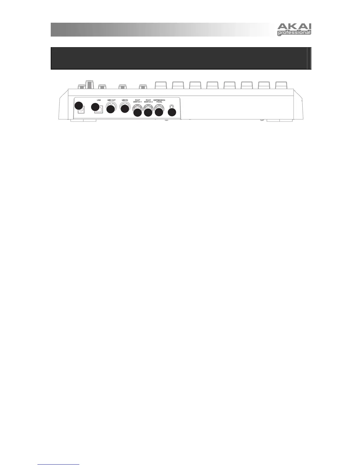
REAR PANEL OVERVIEW
1
2
3
4
5
6
7
8
1. DC POWER ADAPTER INPUT – Plug in a
6V–1A DC power adapter if you do not wish
to power the MPD32 through the USB
connection.
2. USB CONNECTION – Plug a standard USB
cable into this outlet and into the USB port of
your computer. The computer’s USB port will
provide power to the MPD32. This
connection is used to send and receive MIDI
data to and from your computer and may also
be used to send MIDI data from your
computer to a device attached to the MIDI
OUT port of the MPD32.
3. MIDI OUT – Use a five-pin MIDI cable to
connect the MIDI OUT of the MPD32 to the
MIDI IN of an external device.
4. MIDI IN – Use a five-pin MIDI cable to
connect the MIDI OUT of an external MIDI
device to the MIDI IN of the MPD32.
5. FOOT SWITCH 1 – Connect a ¼” TS
footswitch to this input. Footswitches can be
used as MIDI CC switches, or to remotely
control certain features on the MPD32, such
as pad triggering and button events.
6. FOOT SWITCH 2 – Connect a ¼” TS
footswitch to this input. Footswitches can be
used as MIDI CC switches, or to remotely
control certain features on the MPD32, such
as pad triggering and button events.
7. EXPRESSION PEDAL INPUT – Connect a
¼” TRS expression pedal to this input. We
recommend using the Alesis F2 expression
pedals.
8. KENSINGTON LOCK – The unit may be
secured to a table or surface using this
Kensington Lock slot.