Do you have a question about the Akai VS-2EGN and is the answer not in the manual?
Main section introducing the service manual's content and structure.
List of all parts required for servicing the equipment.
Detailed circuit diagrams for troubleshooting and repair.
Procedures for ensuring safety after servicing the unit.
Essential safety precautions to be followed during service operations.
Detailed technical specifications of the VS-2EGN video cassette recorder.
Instructions for operating the VCR, including recording functions.
Step-by-step guide for disassembling the video cassette recorder.
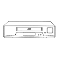
Identification and description of all front and rear panel controls.
Visual guide to the location of major components on the unit.
Instructions for converting the unit's voltage settings for different regions.
Explanation of the unit's circuit functions and TV system compatibility.
Procedures for adjusting mechanical parts like tape guides and rollers.
Adjustments related to tape transport mechanisms for optimal performance.
Procedures for calibrating electrical circuits and settings.
Illustrations of expected waveforms at various test points for diagnostics.
List of PC Board titles and their corresponding part numbers.
Component layouts and diagrams for various PC boards.
Comprehensive list of parts for the VS-2EGN model.
Instructions on how to read and use the provided parts list effectively.
List of critical spare parts recommended for stocking and immediate repair.
Parts breakdown and exploded view of the head drum assembly.
Exploded view and parts list for the mecha frame block.
Parts list and diagram for the ejector block assembly.
Component layout and parts list for the Video (EGN) PC Board.
Component layout and parts list for the Servo (EGN) PC Board.
Component layout and parts list for the Audio/Pre PC Board.
Component layout and parts list for the Demodulator PC Board.
Component layout and parts list for the Power & Sys. Con. PC Board.
Parts list and diagram for the final assembly components.
Component list and diagram for the RC-T2 transmitter unit.
Component list and diagram for the RC-R2 receiver unit.
Schematic diagrams for various integrated circuits used in the unit.
Schematic diagram for the AN6341N IC.
Schematic diagram for the AN6342N IC.
Schematic diagram for the AN6350 IC.
Schematic diagram for the AN6362 IC.
Schematic diagram for the AN6363 IC.
Schematic diagram for the AN6371 IC.
Schematic diagram for the BA222 IC.
Schematic diagram for the BA236 IC.
Schematic diagram for the BA5102 IC.
Schematic diagram for the BA6109 IC.
Schematic diagram for the HD14011B/BP IC.
Schematic diagram for the HD14049BP IC.
Schematic diagram for the HD14053BP IC.
Schematic diagram for the HD14024BP IC.
Schematic diagram for the HD14075BP IC.
Schematic diagram for the HD14093BP IC.
Schematic diagram for the M5144P IC.
Schematic diagram for the M5432P IC.
Schematic diagram for the MSL510P IC.
Schematic diagram for the MB88301-P IC.
Schematic diagram for the MB8841-679J IC.
Schematic diagram for the MN1227P IC.
Schematic diagram for the µPC1373H IC.
Schematic diagram for the µPC339C IC.
Schematic diagram for the µPC574J IC.
Schematic diagram for the µPC741C/TC IC.
Schematic diagram for the µPD1986C IC.
Schematic diagram for the STK-5315 IC.
Schematic diagram for the TA7060AP IC.
Schematic diagram for the TA7075P IC.
Schematic diagram for the TA78L005AP/TA78L012AP ICs.
Schematic diagram for the TC4520BP IC.
Schematic diagram for the µPC1004C IC.
Overall block diagram of the VS-2EGN system.
Block diagram of the Servo circuit for PAL/SECAM systems.
Block diagram of the Servo circuit for NTSC systems.
Block diagram of the Mecha and Operation circuits.
Block diagram of the Power and Syscon circuits.
Block diagram of the Video (EGN) circuit.
Block diagram of the Audio/Video Pre-Amp circuits.
Block diagram of the Demodulator circuit.
Diagram showing interconnections between PCBs.
Schematic diagram for the Video (EGN) PC Board.
Schematic diagram for the EGN PC Board.
Schematic diagram for the Audio/Pre PC Board.
Schematic diagram for the Servo (EGN) PC Board.
Schematic diagram for the Operation PC Board.
Schematic diagram for the Power & Syscon PC Board.
Schematic diagram for the Mecha Drive PC Board.
Schematic diagram for the Demodulator PC Board.
Schematic diagram for the Remote Control Unit.
| Recording Formats | VHS |
|---|---|
| Tuner | Yes |
| Stereo Sound | Yes |
| Hi-Fi Audio | Yes |
| NTSC/PAL | NTSC |
| Remote Control | Yes |
| Type | VCR |
| Playback Formats | VHS |
| Inputs | Composite |
| Outputs | Composite |