Page 48 of 68
These Connectors Are Not Populated
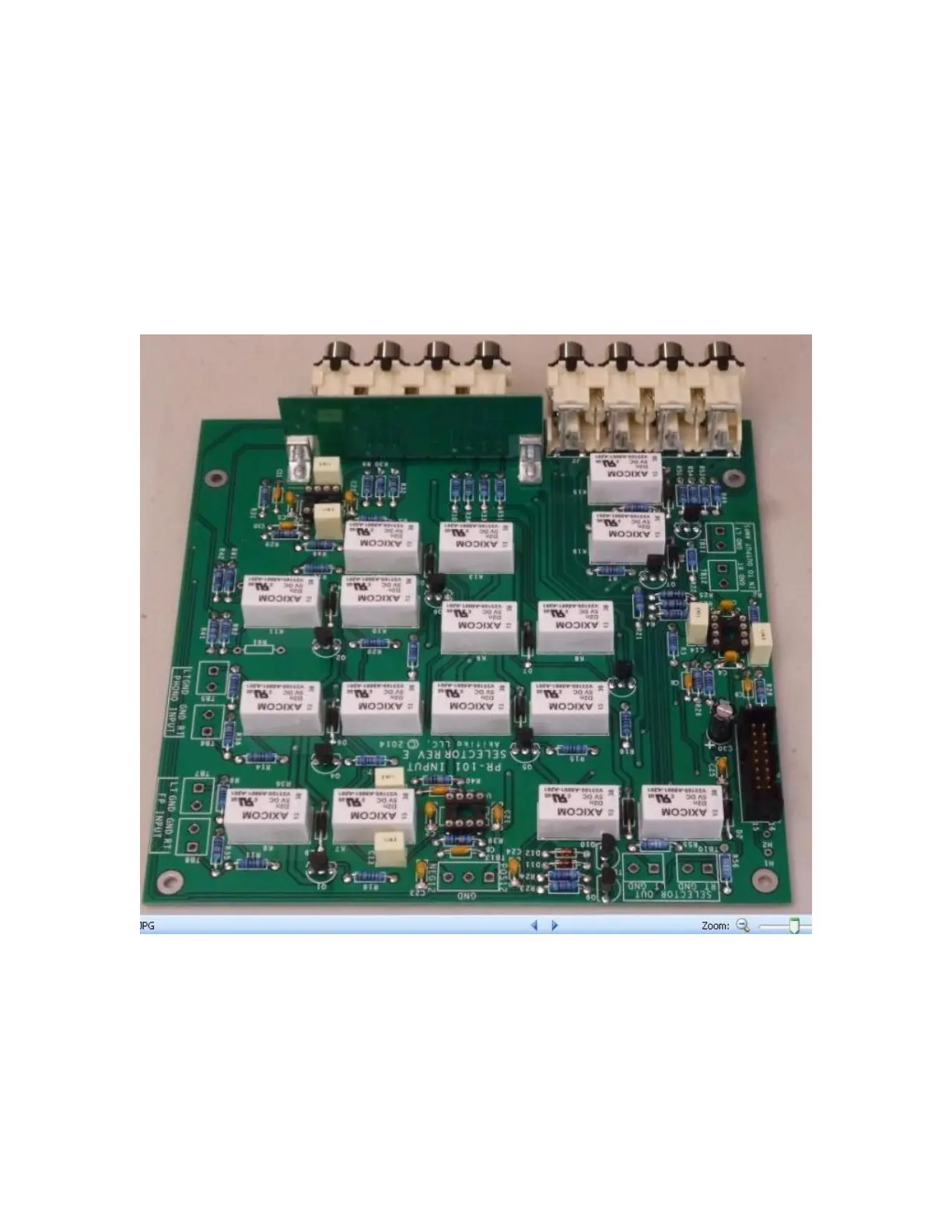
The connectors listed here are not populated. In a later step, you will wire directly to the
PC board.
1. TB5 and TB6 are inputs that can be used if you buy the phono preamp option
card.
2. TB7 and TB8 will be wired to the front panel input connector at a later step
3. TB9 and TB10 will be wired to the input of the tone/volume board in a later step.
4. TB11 and TB12 will be wired to the output of the tone volume board in a later
step
5. TB13 will be wired to plus and minus 12 Volt power and ground in a later step.
Figure 32-Assembled Input Selector board