Page 15 of 80
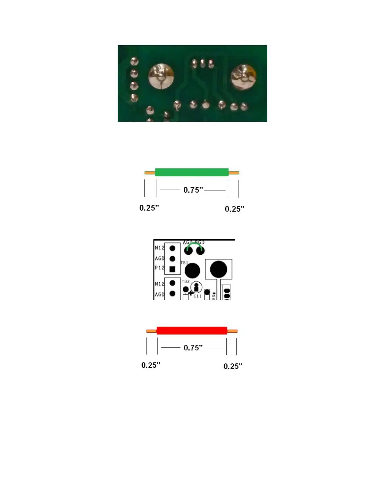
Figure 5-Solder heat sink mounting rods to retain the heat sink
Install the AGD-BGD jumper
Prepare the AGD to BGD jumper wire using some of the 22 AWG solid green wire
supplied with the power supply kit.
Figure 6-Preparing green wire AGD-BGD jumper
Connect AGD and BGD. Insert the green jumper into the AGD and BGD eyelets of the
power supply PCB. Insert it from the component side and solder it on the solder side.
Figure 7-Install AGND to BGND jumper
Prepare two 22 AWG red wires as shown in Figure 8. One will be used to connect AGD
to BGD. The other two will be used for voltage select as described in the next section.
Figure 8-Preparing power supply jumper wires
Install the voltage select jumpers
The PR-102 may be wired for either 120-Volt or 240-Volt operation. This is done by
adding jumpers to the power supply board in the marked places.
Jumper locations are shown in Figure 9.
For 120 Volts, use the left half of Figure 9.
For 240 Volts, use the right half of Figure 9.

 Loading...