EasyManuals Logo

AkitikA PR-102 User Manual

AkitikA PR-102
80 pages
To Next Page IconTo Next Page
To Previous Page IconTo Previous Page
Page #60 background imageLoading...
Page #60 background image
Page 60 of 80
3. Solder the rest of the relay pins.
Designation
Description
Done(
)
K1
DPDT Relay
with 5
-
volt coil
K2
DPDT Relay with 5
-
volt coil
K3
DPDT Relay with 5
-
volt coil
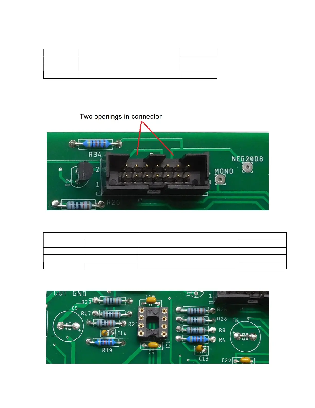
Install the 14-pin cable connector.
Make sure to insert the connector with the correct orientation as shown in Figure 40.
Figure 40-Carefully note the connector orientation
Install the remaining non-polar capacitors
Designation
Value
Marking, description
Done(
)
C1
22nF
22nJ100
C4
22nF
22nJ100
C
2
47nF
47nJ100
C
3
47nF
47nJ100
Although C5 and C6 are laid out to accept 100 µF 35-volt bipolar aluminum electrolytics,
we found superior results by replacing these two capacitors with jumper wires, see Figure
41.
Figure 41-install jumper wires in the C5 and C6 positions

Table of Contents

Questions and Answers:

Question and Answer IconNeed help?

Do you have a question about the AkitikA PR-102 and is the answer not in the manual?

AkitikA PR-102 Specifications

General IconGeneral
BrandAkitikA
ModelPR-102
CategoryAmplifier
LanguageEnglish

Related product manuals