Page 66 of 80
Connect Power to the Tone Volume PCB
Identify the thicker gray cable and green ground wire coming from TB4 on the power
supply board.
12V power and AGND to the Tone Volume Board
insulation from the red wire.
Tightly twist the red wire strands, then tin them.
Remove ¼” of insulation from the black wire.
Tightly twist the black wire strands, then tin them.
Remove ¼” of insulation from the green wire.
green wire strands, then tin them.
Insert the tinned green wire into the GND hole of the Tone Volume’s J2.
Insert the wire into the solder side of the PCB, and solder it on the
Insert the tinned red wire into the POS12 hole of the Tone Volume’s J2.
Insert the wire into the solder side of the PCB, and solder it on the
Insert the tinned black wire into the NEG12 hole of the Tone Volume’s J2.
Insert the wire into the solder side of the PCB, and solder it on the
Double check the locations of the red and black wires to avoid a costly mistake.
Tone Volume Signal Wiring
In this section you’ll connect the already existing shielded signal cables from the input
selector board to the tone volume board. Insert the wires into the solder side of the board
and solder on the component side.
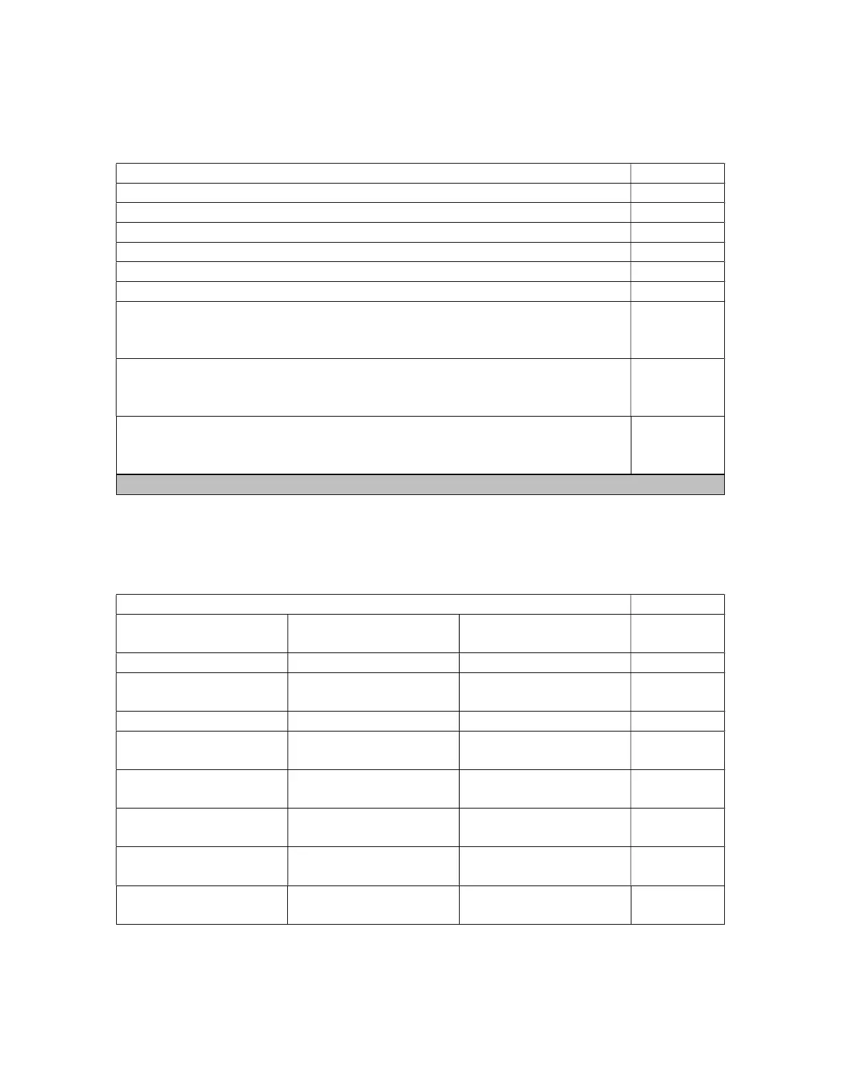
Connecting Signal wires to the Input Se
From Input Selector
To Tone Volume
What?
SELECTOR OUT,
J1, LEFT GND Drain wire with gray
SELECTOR OUT,
J3, RIGHT GND Drain wire with gray
IN TO OUTPUT
J5, RIGHT OUT Red wire
IN TO OUTPUT
J5, RIGHT GND Drain wire with gray
IN TO OUTPUT
J4, LEFT OUT Black wire
IN TO OUTPUT
J4, LEFT GND Drain wire with gray

 Loading...