Page 55 of 80
If the voltages are correct, go onto the next step. If the voltages are not in tolerance,
review your work for errors, particularly backwards electrolytic caps or backwards ICs in
the input selector board. Do not go farther until the voltages are correct. If you reach a
road-block, send email to dan@akitika.com for troubleshooting advice.
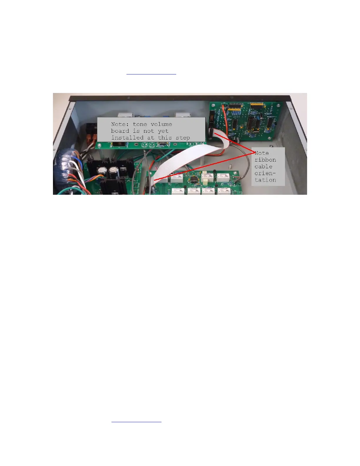
Install 16 pin ribbon cable
Figure 36-16 pin ribbon cable orientation and installation
Here is the input selector control interface test procedure:
1. Locate the 16-pin ribbon cable from the wire kit. Note that the ribbon cable has
keyed connectors.
2. Refer to Figure 36 for the cable orientation. Note that the red stripe on the cable
faces up when connecting to the controller.
3. Touch the chassis first. You may get a static electricity shock, but better you than
the controller (it has protection, but let’s avoid exercising it).
4. Connect one end of the cable into the accompanying socket on the input selector
PCB. Don’t force the connector…if it doesn’t go, re-check the connector’s
orientation.
5. Connect the other end of the cable into the accompanying socket on the controller
board.
Test Input Selector Control Interface
1. Connect the IEC power cord to the PR102 and the AC mains (wall socket).
2. Switch on the AC power.
3. Wait a few seconds after power up.
4. Push the up and down arrow buttons on the input selector. Each push should
produce an audible mechanical thump from the associated input selector relays.
5. Push the AMP A and AMP B buttons. A somewhat softer audible mechanical
thump should result from the operation of the associated relay.
6. Push the Tape 1 Mon and Tape 2 Mon buttons. A somewhat softer audible
mechanical thump should result from the operation of the associated relay.
7. Disconnect the IEC power cord and switch off the AC power.
If the relays activate as described above, proceed to the next section. If you reach a road-
block, send email to dan@akitika.com for troubleshooting advice.