Page 33 of 80
Install the IC’s and Transistor
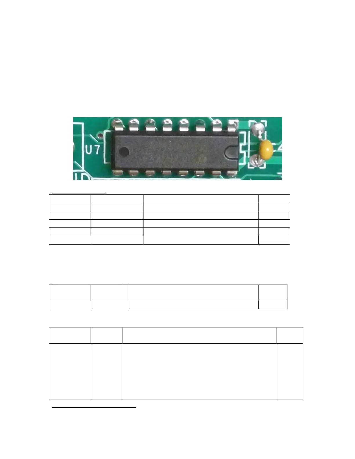
Make sure to orient the IC’s correctly when you install them. After you install each IC,
bend over two diagonally opposed leads to retain the IC. Then double check to make sure
that:
You have the correct IC in the correct location.
The IC is oriented correctly.
Solder the rest of the IC pins after you have double checked its type and
orientation.
Figure 22-Insert all the IC’s so that the U-shaped indent matches the silk-screen
Integrated Circuits
2
bit serial in parallel out shift register
bit serial in parallel out shift register
bit parallel in serial out shift register
bit parallel in serial out shift register
Caution: Don’t confuse U5 and Q1. They are both in very similar looking TO-92
packages. Look carefully at their markings.
Regulator and Transistor
U5 LP2950 3.3 volt regulator, TO-92 package, marked
0 volt NPN transistor, TO
Install the Resistor Networks
Designation Value Description Done
RN1 8 10K
resistors
Install RN1 in the indicated place. Make sure that
pin 1 of RN1, marked by the dot, goes into pin 1 of
the RN1 hole pattern on the PCB, indicated by a
square pad on the PCB. Solder the two end pins
first to make sure that RN1 is sitting level on the
board. Once RN1 is level, solder the balance of the
2
There may be other text on the IC, but if you see the indicated text then all is well.