Page 47 of 80
Designation Value Description Done
volt ceramic capacitor, marked 104
100 volt ceramic capacitor, marked 104
100 volt ceramic capacitor, marked 104
100 volt ceramic capacitor, marked 104
ceramic capacitor, marked 104
100 volt ceramic capacitor, marked 104
100 volt ceramic capacitor, marked 104
100 volt ceramic capacitor, marked 104
ceramic capacitor, marked 104
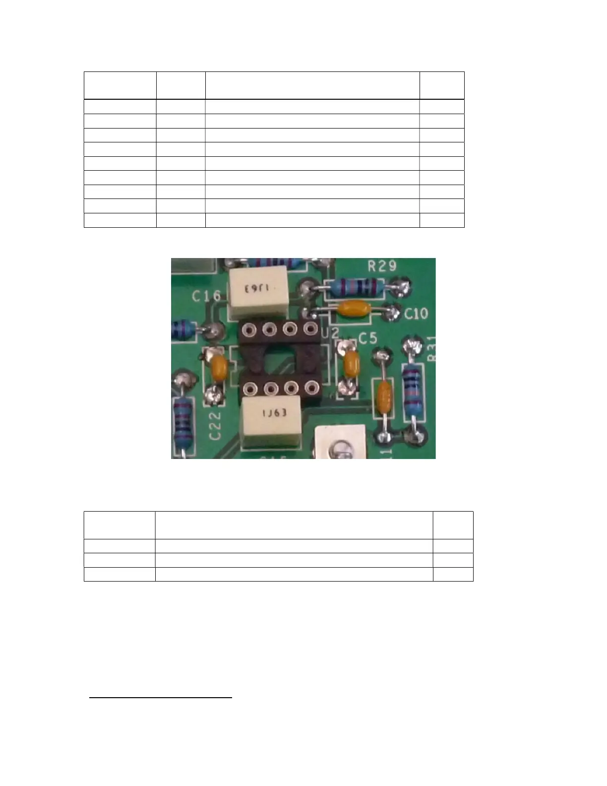
Install the Integrated Circuit Sockets
Figure 31-Align socket feature with silk screen
We’ve supplied IC sockets for the op-amps that have gold-plated pins. They may be
found in the “PR102 Opamp Sockets” envelope. You’ll install the 3 IC sockets now. The
actual ICs will be installed in a later step
6
.
Designation Watch IC socket orientation! See Figure 31 Done
Solder an 8 pin IC socket in place
Solder an 8 pin IC socket in place
Solder an 8 pin IC socket in place
Install the Control Cable Connector
Look at Figure 32 CAREFULLY to be sure that you’re installing P1 correctly! Match the
indicated features of the connector to the picture.
6
3 more sockets will be installed at a later step when the tone-volume board is built.