Following assembly of the wheels, it is
recommended to assemble the additional wheel
foot (3) for stability and to keep the generator on a
level surface.
1. Raise the opposite end of the generator that the
wheels have been assembled on by placing a
wooden block (or something similar) underneath
the bracket that the feet have been assembled on
(Fig B).
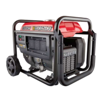
2. Insert the supplied hex head screw through the
bottom of the foot so it comes out the opposite
side (Fig H).
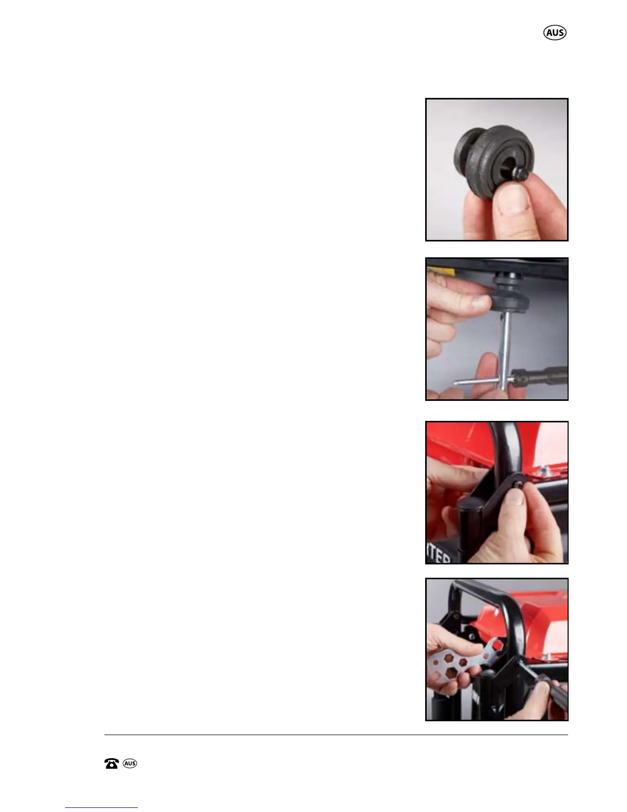
Using the supplied 10mm tube spanner (30), insert
into the foot and engage the head on the hex
head screw. Thread the hex head screw into the
large boss on the base frame cross member on the
handle end of the generator (Fig I). Tighten firmly.
Assembly of the Folding Carry Handle
This generator is supplied with a folding carry handle
(6) to assist with transportation when wheeling the
generator around on the wheels.
1. Align the holes on each bracket of the carry handle
with the holes on each side of the generator frame
(Fig J).
2. With the handle in position, insert each screw
through the outer bracket of the handle, then
through the holes in the generator frame, and
through to the opposite side of the internal
bracket of the handle.
3. Secure the handle into position by applying the
nyloc nuts onto the screws and securing
finger tight.
Using the supplied double ended screwdriver
(phillips head) (32) to hold the screw, then use the
multi size spanner (33) in a clockwise direction to
secure the nyloc nut in place (Fig K).
H.
J.
K.
I.
General Assembly