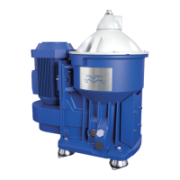
4 Design and function
1
2
3
4
5
6
7
G08706w1
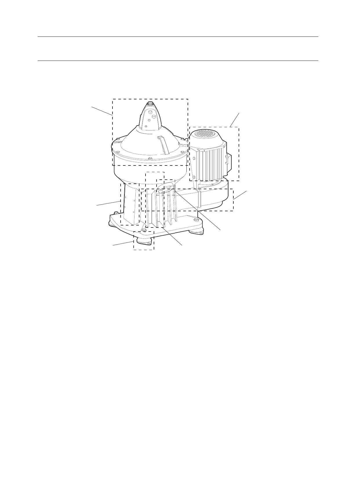
1. Process section
The feed inlet and outlets are situated at the top of the separator. The liquid is cleaned in the
rotating separator bowl inside the frame hood.
2. Sensors
The separator is monitored by a speed sensor. An unbalance sensor and an interlocking
switch are optional.
3. Frame feet
The separator rests on vibration damping frame feet.
4. Lubrication system
Lubricates the bearings driven by the flat belt transmission.
5. Sludge outlet
Separated solids are discharged at preset intervals.
6. Drive section
The rotating separator bowl is driven by a flat belt transmission with friction coupling.
7. Electric motor
Rotating bowl is driven by the electric motor via a belt transmission.
21