4 Design and function 4.3 The Process Section
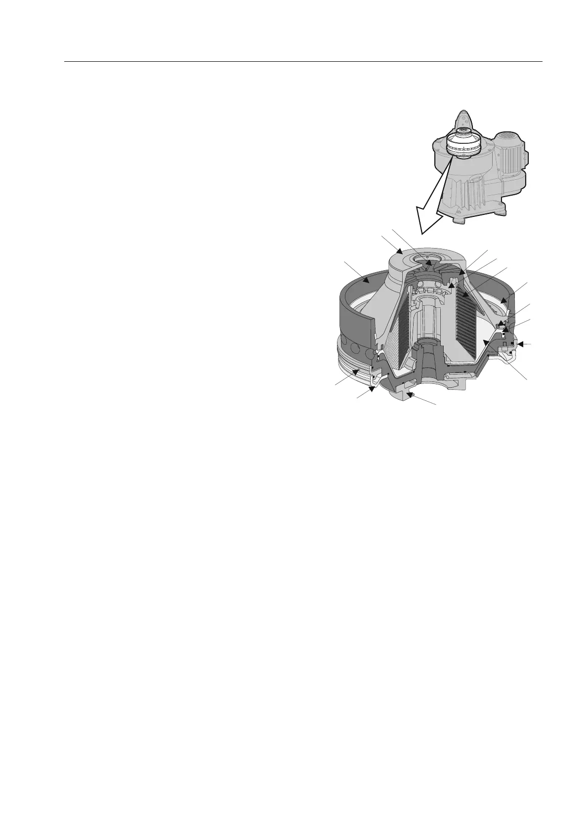
Separator bowl
The separator bowl, with its sludge discharge
mechanism, is built-up as follows:
The bowl body and bowl hood are held together
by a lock ring (Centrilock). Inside the bowl are
the distributor and the disc stack. The disc
stack is kept compressed by the bowl hood.
The discharge slide forms a separate bottom
in the bowl body.
The upper space between the bowl hood and
the top disc forms the water paring chamber
and contains the paring tube, which pumps the
separated water out of the bowl. The oil paring
chamber, with its paring disc, is located inside
the top of the distributor. From here the cleaned
oil is pumped out of the bowl.
The sludge space is in the bowl periphery. The
bowl is kept closed by the discharge slide, which
seals against a seal ring in the bowl hood.
At fixed intervals, decided by the operator, the
discharge slide drops down to empty the bowl
of sludge.
The sludge discharge mechanism, which
controls the movement of the discharge slide,
is comprised of an operating slide and an
operating water device. Passive parts are:
nozzle and valve plugs. The operating wat
er
cover, beneath the bowl, supplies opera
ting
water to the discharge mechanism via th
e
operating water ring.
1
2
3
4
5
6
7
8
9
10
11
12
13
14
G08869a1
1. Top disc
2. Oil par ing chamber
3. Disc stack
4. Lock r ing
5. Seal ring
6. Discharge slide
7. Operating slide
8. Sludge space
9. Operating water ring
10. H older
11. Nozzle
12. B owl body
13. B owl hood
14. Water paring chamber
25