3.4 Electrical installation, AS-interface
1
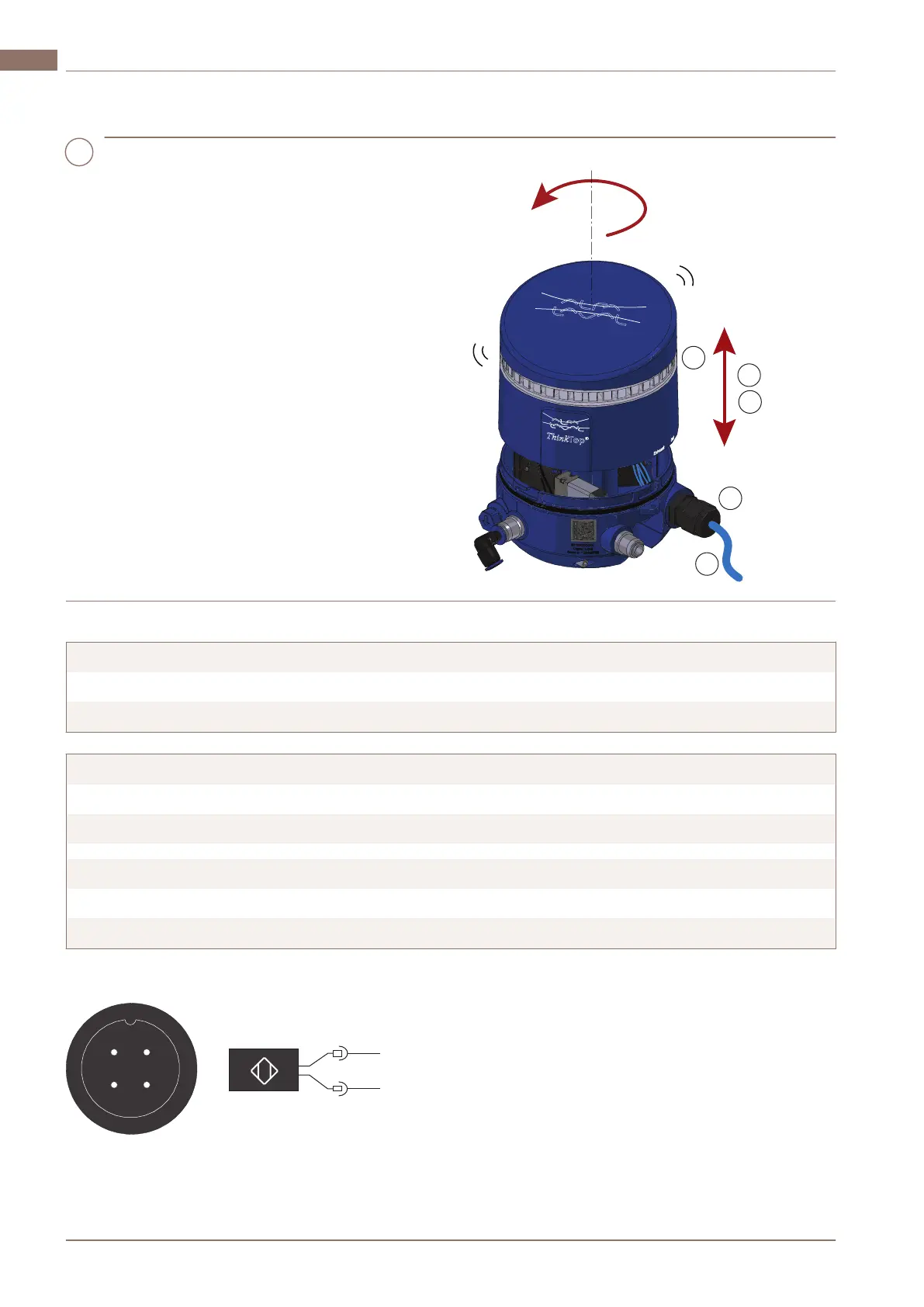
a) Remove the top cover by turning it
counter clockwise and then lifting it
upwards.
b)
To allocate an address, use your preferred
addressing device. See the device
manual for more information.
c) Connect the cable to the ThinkTop, and
then connect the wires to the terminals
according to the wiring diagram.
d) Tighten the cable gland using a 19 mm
wrench (1…3 Nm).
Or tighten the M12 connector using a 14
mm wrench (0.6...1.5 Nm).
e) Put the top cover back in place.
f) Turn on the power supply.
If installed correctly, the light guide flashes
green.
Wiring diagrams
Terminals V50 AS-interface
1 AS-i supply AS-i + (brown)
2 AS-i supply AS-i – (blue)
Terminals V70 AS-interface
1 AS-i supply AS-i + (brown)
2 AS-i supply AS-i – (blue)
1 Seat lift sensor Supply (brown)
2 Seat lift sensor GND (blue)
3 Seat lift sensor Signal (black and white)
M12 option (4-pin A-coded plug):
2066-0053
1
4
2
3
AS-i +
AS-i -
1
3
BN
BU
200000549-1-EN-GB14
3 InstallationEN
www.sks-online.com
www.sks-webshop.com
 Loading...