Steps
1. Remove the two screws (M1.6x1.8) that secure the display-cable bracket to the system board.
2. Lift the display-cable bracket off the system board.
3. Disconnect the display cable from the system board.
4. Turn the computer over.
5. Remove the four screws (M2x4) that secure the display-cable holder to the palm-rest and keyboard assembly.
6. Rotate the display-cable holder to 180 degrees.
7. Remove the display cable from the display-cable holder and lift the display-cable holder off the palm-rest and keyboard
assembly.
NOTE: While removing the display cable from the display cable holder, push open the spring-loaded bar separating the two
slits in the middle of the display holder.
8. Remove the six screws (M2.5x5) that secure the display assembly to the palm-rest and keyboard assembly.
9. Slide the display cable from the slot between the palm-rest and keyboard assembly and rear I/O cover.
10.Slide the display assembly off the palm-rest and keyboard assembly.
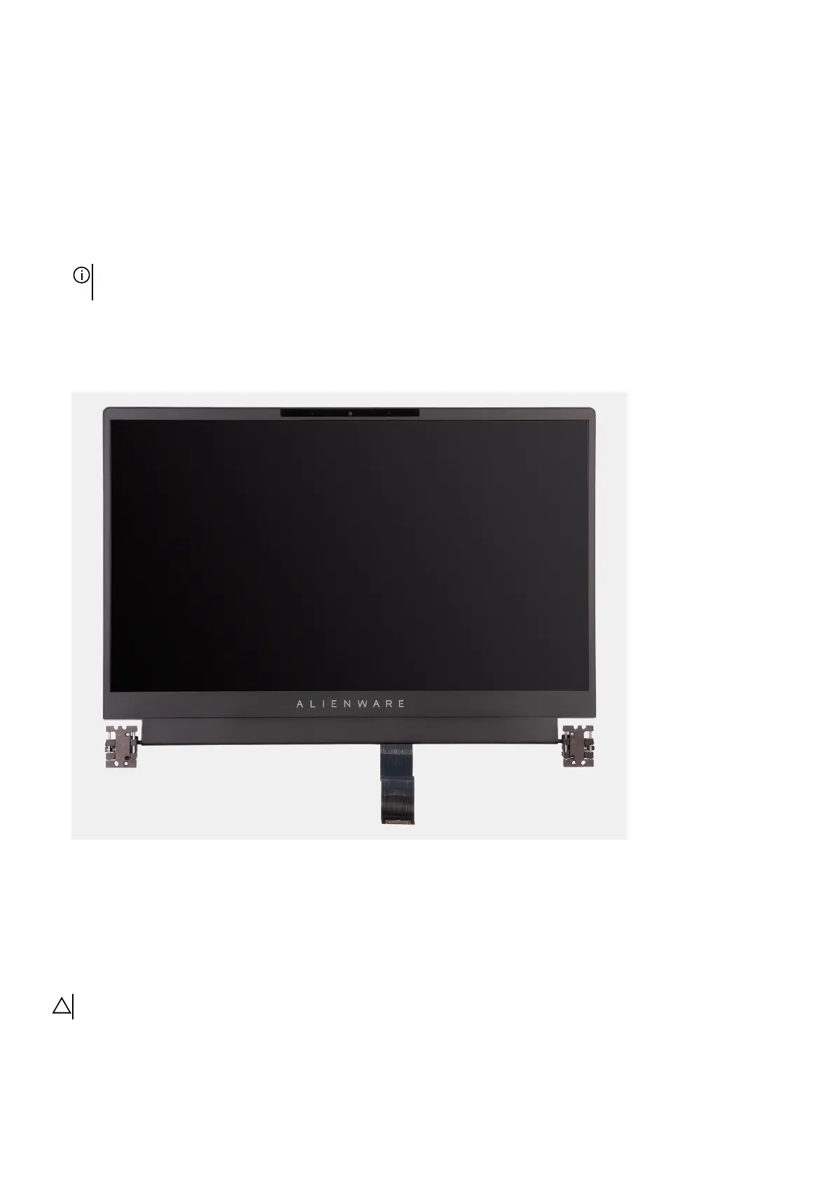
11. After performing the steps above, you are left with the display assembly.
Installing the display assembly
Prerequisites
If you are replacing a component, remove the existing component before performing the installation process.
About this task
CAUTION: Place the computer on a soft and clean surface to avoid scratching the display.
The following image(s) indicate the location of the display assembly and provides a visual representation of the installation
procedure.
37