Steps
1. Remove the two screws (M1.6x1.8) that secure the display-cable bracket to the system board.
2. Disconnect the display cable from the system board.
3. Lift the Mylar to access the I/O-board cable.
NOTE: The I/O-board connector is covered by the Mylar. In order to disconnect the I/O-board cable, the Mylar must be
lifted to access the connector.
4. Open the latch and disconnect the I/O-board cable from the system board.
5. Open the latch and disconnect the headset-port cable from the system board.
6. Peel the headset-port cable from the system board.
7. Open the latch and disconnect the power-button cable from the system board.
8. Disconnect the speaker cable from the system board.
9. Open the latch and disconnect the keyboard-controller board-cable from the system board.
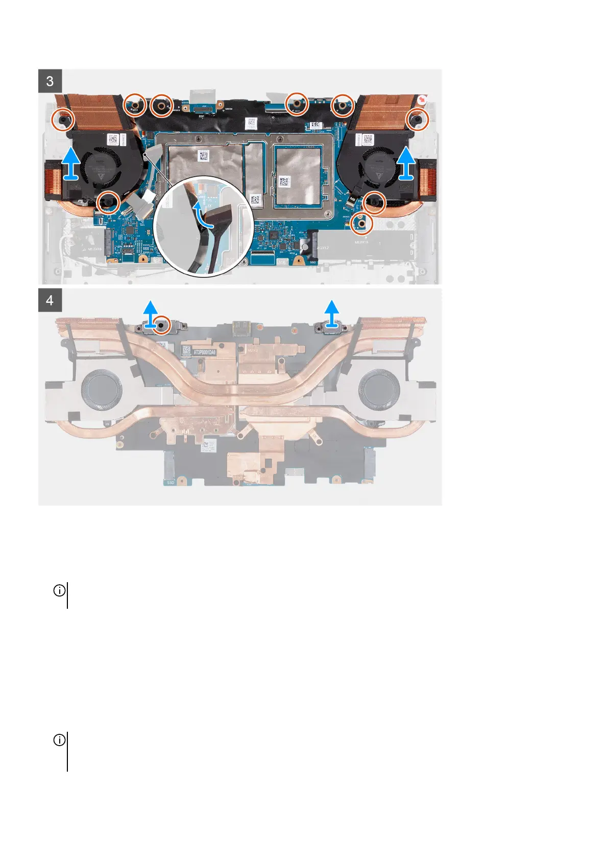
10.Remove the nine screws (M2x4) that secure the system-board assembly to the palm-rest and keyboard assembly.
11. Route the headset-port cable through the gap between the system board and the left fan.
NOTE: When lifting the system-board assembly from the palm-rest and keyboard assembly, grab and lift the system-board
assembly holding the heat sink on both sides carefully, by routing the headset-port cable from the gap between the system
board and the left fan.
44