3–2 Configuration and Interfacing
Publication 1203–5.1 –– July, 1997
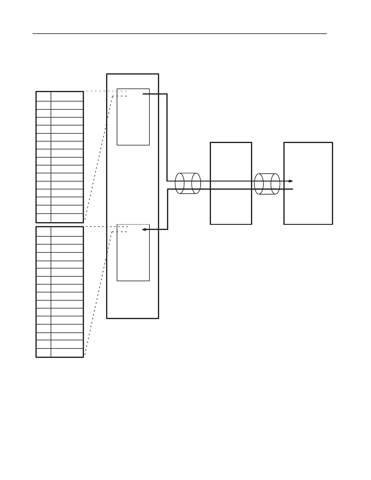
Figure 3.1
Typical Example of Data Transfer Through the Communications Module
00
Programmable Controller
I/O Image Table
01
02
03
04
05
06
07
11
12
13
14
15
16
17
00
01
02
03
04
05
06
07
11
12
13
14
15
16
17
Rack 2
Output Image
Word 0
Word 1
Word 2
Word 3
Word 4
Word 5
Word 6
Word 7
Word 0
Word 1
Word 2
Word 3
Word 4
Word 5
Word 6
Word 7
Rack 2
Input Image
Remote I/O
Logic Command/
Status Enabled
SCANport
1336 PLUS
Drive
Logic Command
Logic Status
Remote I/O
Communications
Module
Stop
Start
Jog
Clear Faults
Direction
Direction
Local
Mop Increment
Accel Time
Decel Time
Enabled
Running
Cmd Direction
Actual
Direction
Accelerating
Decelerating
Alarm
Faulted
At Speed
Local
Local
Local
Accel Time
10
Decel Time
Ref Select
Ref Select
Ref Select
MOP Decrement
10
Ref Select
Ref Select
Ref Select
Ref Select
This is a typical example of data transfer from a PLC to a 1336
PLUS drive. Refer to the manual provided with your
SCANport–compatible product for actual Control and Status words.
Important: The communications module does not scale the data
that is transferred. If data in the programmable
controller is manipulated in units other than device
units, the data must first be converted before being sent
to the device. Consequently, all scaling of the data must
be done in the PLC. Refer to the appropriate SCANport
device manual for details on device units.
"

 Loading...