Rockwell Automation Publication 1420-UM001E-EN-P - March 2016 41
Communication Chapter 4
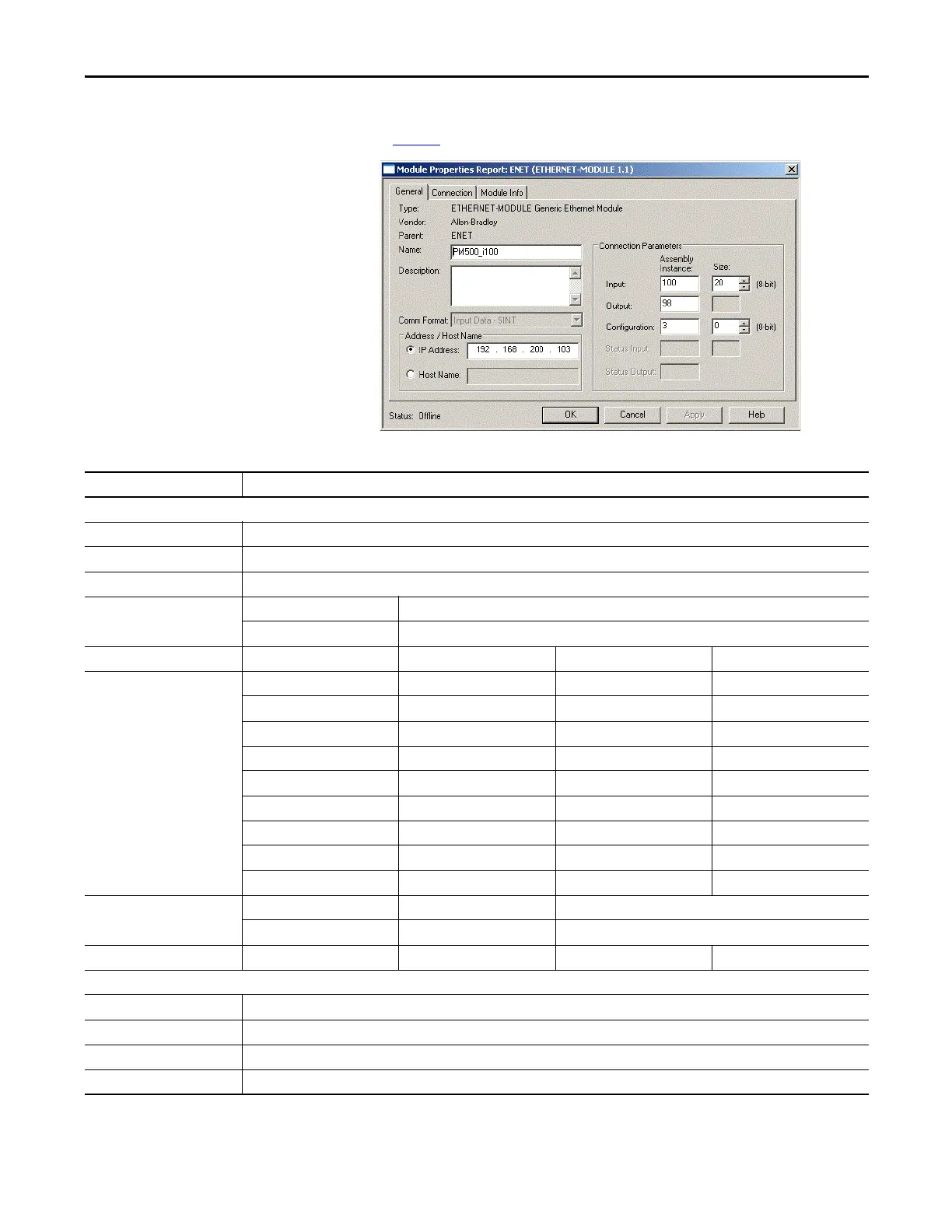
4. Enter the setup parameters as listed in this dialog box and explained in
Table 7
.
Table 7 - Module Properties Setup Parameters
Item Choices
General Tab
Name Required; must be IEC 1131-3 compliant
Description Optional
Comm Format Depends on selected Assembly Instance
(1)
Address/Host Name IP Address IP address of target PowerMonitor 500 unit
Host Name Not applicable
Connection Parameters Assembly Instance Size Comm Format Data Table Description
Input (select one) 100 20 Input Data - SINT Product Information
101 12 Input Data - REAL Real-time Voltage and Current
102 18 Input Data - REAL Real-time Power, PF, Frequency
103 12 Input Data - REAL Max Voltage and Current
104 17 Input Data - REAL Max Power, PF, Frequency
105 12 Input Data - REAL Dmd Voltage and Current
106 17 Input Data - REAL Dmd Power, PF, Frequency
107 18 Input Data - REAL Energy Meters
108 2 Input Data - INT Alarm and Output Status
Output 98 N/A Inst. 98 used for Input Only connection
99 N/A Inst. 99 used for Listen Only connection
(1)
Configuration 3 0 Instance 3 is a placeholder only
Connection Tab
RPI 100 ms or greater
Inhibit Module Optional - unchecked by default
Major Fault Optional - unchecked by default
Unicast Connection Optional - checked by default
(1) Use the Listen Only connection only when an Input Only connection exists with another controller.
 Loading...


