Rockwell Automation Publication 1734-UM013N-EN-P - September 2017 77
Install the Module Chapter 4
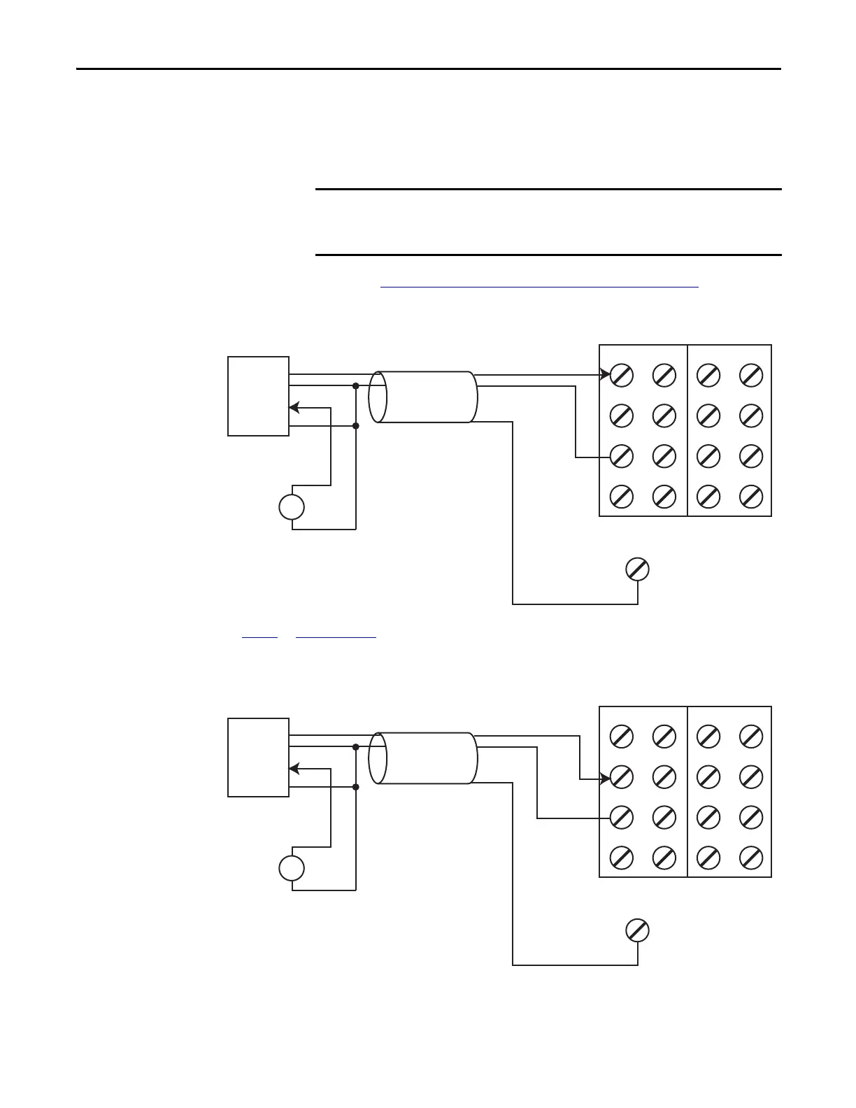
In the following two examples, the negative terminal of the sensor power supply
and that of the 1734 terminal base COMMON must be at the same potential.
Use of an external power supply limits diagnostics and increases susceptibility to
noise.
Follow the Guidelines for Wiring Safety Analog Inputs
on page 71.
Figure 45 - 4-wire Voltage or Tachometer Sensor (SIL 2) with External Power Supply
Figure 46 - 4-wire Current Sensor (SIL 2) with External Power Supply
You are responsible for making sure that the sensor is receiving appropriate
power. Safety sensors that are not properly powered do not always deliver
accurate signals to the analog input module.
V0
DC
V1 V2 V3
I0 I1 I2 I3
COM COM COM COM
S0
FE
S1 S2 S3
+
-
Signal Return and Common are at the same potential.
1734-TB Terminal Bases
Signal (V)
+24V
Cable Shield
Signal Return
4-wire
Sensor
See Figure 47
and Figure 48 on page 78 for tachometer wiring detail.
V0
DC
V1 V2 V3
I0 I1 I2 I3
COM COM COM COM
S0
FE
S1 S2 S3
+
-
Signal Return and Common are at the same potential.
1734-TB Terminal Bases
Signal (V)
+24V
Cable Shield
Signal Return
4-wire
Sensor
 Loading...


