EasyManua.ls Logo

Allen-Bradley 1734-OBV2S User Manual

Allen-Bradley 1734-OBV2S
235 pages
To Next Page IconTo Next Page
To Previous Page IconTo Previous Page
Page #225 background imageLoading...
Page #225 background image
Rockwell Automation Publication 1734-UM013N-EN-P - September 2017 225
I/O Assemblies Appendix F
Using Data from Modules
Configured Via the Generic
Profile
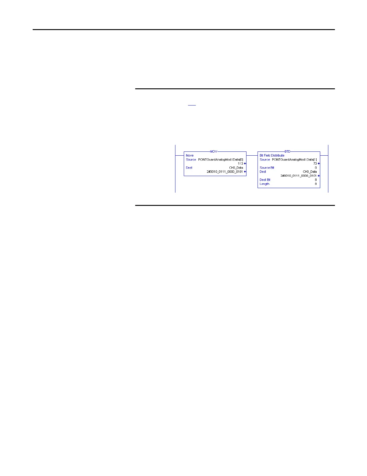
To use I/O assembly data from a 1734-IE4S module that is configured via the
Generic Profile in your application program, you must first combine the input
data from two SINTs into one INT. The following example shows one method
for converting the data by using a Move instruction and a Bit Field Distribute
instruction.
EXAMPLE
This example uses Input Assembly Instance 802, which is described on
page 218
.
POINTGuardAnalogMod.I.Data[0] = Channel 0 Low Byte (SINT)
POINTGuardAnalogMod.I.Data[1] = Channel 0 High Byte (SINT)
CH0_Data = Combined Channel 0 data (INT) that can be used in an
application program

Table of Contents

Question and Answer IconNeed help?

Do you have a question about the Allen-Bradley 1734-OBV2S and is the answer not in the manual?

Allen-Bradley 1734-OBV2S Specifications

General IconGeneral
Product TypeOutput Module
Series1734
Number of Outputs2
Output TypeSourcing
Enclosure Type RatingIP20
ManufacturerRockwell Automation/Allen-Bradley
Connection TypeSpring Clamp
Operating Temperature-20°C to 55°C
CertificationsCE
Isolation Voltage50V
Weight0.1 kg
Operating Voltage10-30V DC
Output Current0.5A per point

Summary

Chapter 1 POINT Guard I/O Overview

Safety Precautions

Outlines essential safety measures to prevent injury or equipment damage during product use.

POINT Guard I/O Modules in CIP Safety Systems

Explains the integration of POINT Guard I/O modules within CIP Safety systems.

Safety Application Requirements

Details the requirements for implementing safety applications with these modules.

Chapter 2 Safety Inputs, Safety Outputs, and Safety Data

Safe States

Defines the safe states for digital and analog POINT Guard I/O modules.

Safety Inputs (1734-IB8S)

Discusses the use and configuration of safety inputs for the 1734-IB8S module.

Dual-channel Mode and Discrepancy Time

Explains dual-channel operation and how discrepancy time affects fault detection.

Dual-channel, Equivalent

Describes the operation and fault detection in dual-channel equivalent mode.

Dual-channels, Complementary

Explains the operation and fault detection in dual-channel complementary mode.

Safety Analog Inputs (1734-IE4S)

Covers configuration and operation of the 1734-IE4S analog input module.

Dual-channel Equivalent Mode

Details the operation and fault detection for dual-channel equivalent mode of analog inputs.

Safety Outputs (1734-OB8S and 1734-OBV2S)

Covers the configuration and operation of safety outputs for these modules.

Safety Output with Test Pulse

Details the functionality and use of pulse testing for safety outputs.

Dual-channel Mode

Explains the operation of safety outputs in dual-channel mode.

Single-channel Mode, 1734-OB8S Only

Describes the operation of safety outputs in single-channel mode for the 1734-OB8S module.

Chapter 3 Guidelines for Placing Power Supplies and Modules in a System

Chapter 4 Install the Module

Precautions

Lists crucial precautions to follow before and during module installation.

Mount the Module

Outlines the steps for mounting the module, including installing the base.

Connect the Module to the Mounting Base

Explains how to physically connect the module to its mounting base using keyswitches.

Wire Modules

Provides guidelines and precautions for wiring the modules correctly.

Wiring Examples

Presents examples of wiring configurations for specific applications.

Emergency Stop Dual-channel Devices

Shows wiring and configuration for dual-channel emergency stop devices.

Bipolar Safety Outputs

Provides examples of wiring 1734-OBV2S bipolar outputs for PLe and PLd safety.

Safety Analog Input Wiring

Offers guidelines and examples for wiring safety analog inputs.

Chapter 5 Configure the Module in a GuardLogix Controller System

Set up the Module

Details the initial setup process for POINT Guard I/O modules in a GuardLogix system.

Add and Configure the Ethernet Bridge

Explains how to add and configure an Ethernet bridge module in the controller project.

Add and Configure the 1734 Ethernet Adapter

Guides on adding and configuring the 1734 Ethernet adapter for network communication.

Add and Configure Safety Digital Input Modules

Describes how to add and configure safety digital input modules in the project.

Configure the Safety Digital Inputs

Details the process of configuring safety digital input parameters.

Add and Configure Safety Digital Output Modules

Guides on adding and configuring safety digital output modules in the controller project.

Configure the Safety Digital Outputs

Details the process of configuring safety digital output parameters.

Add and Configure Safety Analog Input Modules

Guides on adding and configuring safety analog input modules in the project.

Configure the Safety Analog Input Channel Operation

Explains how to configure the operation type and parameters for safety analog input channels.

Configure the Safety Analog Inputs

Details how to assign point modes and configure input types for safety analog inputs.

Configure Tachometer Operation

Guides on configuring the module for tachometer operation and dual low detection.

Configure Safety Connections

Details how to configure safety connections between the controller and I/O modules.

Chapter 6 Configure the Module for a SmartGuard Controller

Set the Node Address

Explains how to set the node address for POINT Guard I/O modules using RSNetWorx.

Configure the POINT Guard I/O Modules

Details the process of configuring POINT Guard I/O modules within RSNetWorx.

Configure Digital Safety Inputs and Test Outputs

Explains how to configure digital safety inputs and test outputs in RSNetWorx.

Configure Digital Safety Outputs

Guides on configuring digital safety output parameters in RSNetWorx.

Configure Safety Analog Inputs

Details how to configure safety analog inputs for the 1734-IE4S module in RSNetWorx.

Configure the SmartGuard Controller

Covers the steps to configure the SmartGuard controller and its connections.

Chapter 7 Configuring Safety Connections between a GuardLogix Controller and POINT Guard I/O Modules on a DeviceNet Network

Configure the Module in RSNetWorx for DeviceNet Software

Outlines the tasks required in RSNetWorx to configure modules for DeviceNet.

Add the POINT Guard I/O Module to the Controller Project

Guides on adding POINT Guard I/O modules to the GuardLogix controller project using Logix Designer.

Chapter 8 Replacing POINT Guard I/O Modules

Replace a Module in a GuardLogix System on an EtherNet/IP Network

Covers replacing modules in GuardLogix systems over an EtherNet/IP network.

Replace a Module When Using a SmartGuard or GuardLogix Controller on a DeviceNet Network

Details module replacement for SmartGuard or GuardLogix controllers on a DeviceNet network.

Appendix B Get I/O Diagnostic Status from Modules in Logix Systems

Appendix D Safety Data

Related product manuals