Publication 1769-UM009B-EN-P - May 2002
3-8 Installation and Wiring
Panel Mounting
Mount the module to a panel using two screws per module. Use M4
or #8 panhead screws. Mounting screws are required on every
module.
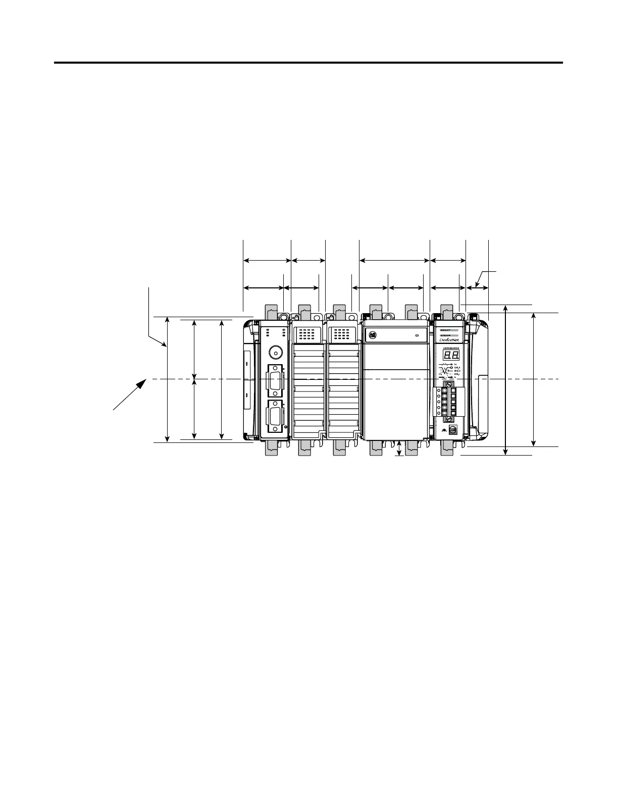
Panel Mounting Using the Dimensional Drawing
NOTE: All dimensions are in mm (inches). Hole spacing tolerance: ±0.4 mm (0.016 in.).
Compact I/O with CompactLogix Controller and Power Supply
132 mm (5.19 in)
122.6 mm (4.83 in)
118 mm (4.65 in)
147.4 mm (5.81 in)
14.7 mm
(0.58 in)
35 mm
(1.38 in)
35 mm
(1.38 in)
28.5 mm
(1.12 in)
35 mm
(1.38 in)
70 mm
(2.76 in)
35 mm
(1.38 in)
35 mm
(1.38 in)
35 mm
(1.38 in)
50 mm
(1.97 in)
40 mm
(1.58 in)
59 mm
(2.32 in)
59 mm
(2.32 in)
DIN Rail
Center Line
Mounting Hole
Dimension

 Loading...


