Publication 1769-UM009B-EN-P - May 2002
Installation and Wiring 3-9
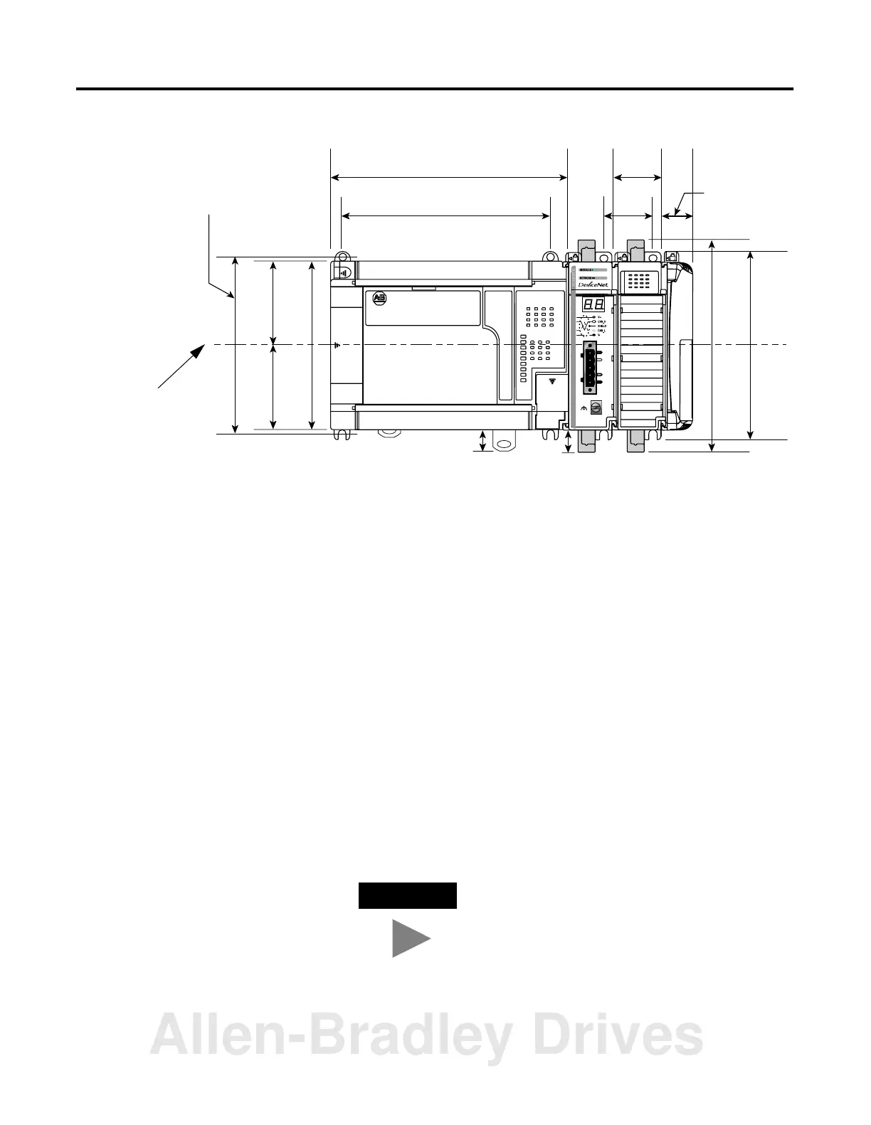
Compact I/O with MicroLogix 1500 Base Unit and Processor
Panel Mounting Procedure Using Modules as a Template
The following procedure allows you to use the assembled modules as
a template for drilling holes in the panel. Due to module mounting
hole tolerance, it is important to follow these procedures:
1. On a clean work surface, assemble no more than three modules.
2. Using the assembled modules as a template, carefully mark the
center of all module-mounting holes on the panel.
3. Return the assembled modules to the clean work surface,
including any previously mounted modules.
4. Drill and tap the mounting holes for the recommended M4 or #8
screw.
5. Place the modules back on the panel, and check for proper hole
alignment.
6. Attach the modules to the panel using the mounting screws.
7. Repeat steps 1 to 6 for any remaining modules.
132 mm (5.19 in)
122.6 mm (4.83 in)
118 mm (4.65 in)
147.4 mm (5.81 in)
14.7 mm
(0.58 in)
35 mm
(1.38 in)
168 mm
(6.62 in)
147 mm
(5.79 in)
35 mm
(1.38 in)
13.5 mm
(0.53 in)
59 mm
(2.32 in)
59 mm
(2.32 in)
28.5 mm
(1.12 in)
DIN Rail
Center Line
Mounting Hole
Dimension
TIP
If mounting more modules, mount only the last
one of this group and put the others aside. This
reduces remounting time during drilling and
tapping of the next group.
Allen-Bradley Drives

 Loading...


