10 Rockwell Automation Publication 1783-IN013B-EN-P - December 2019
Stratix 5800 Ethernet Managed Switches
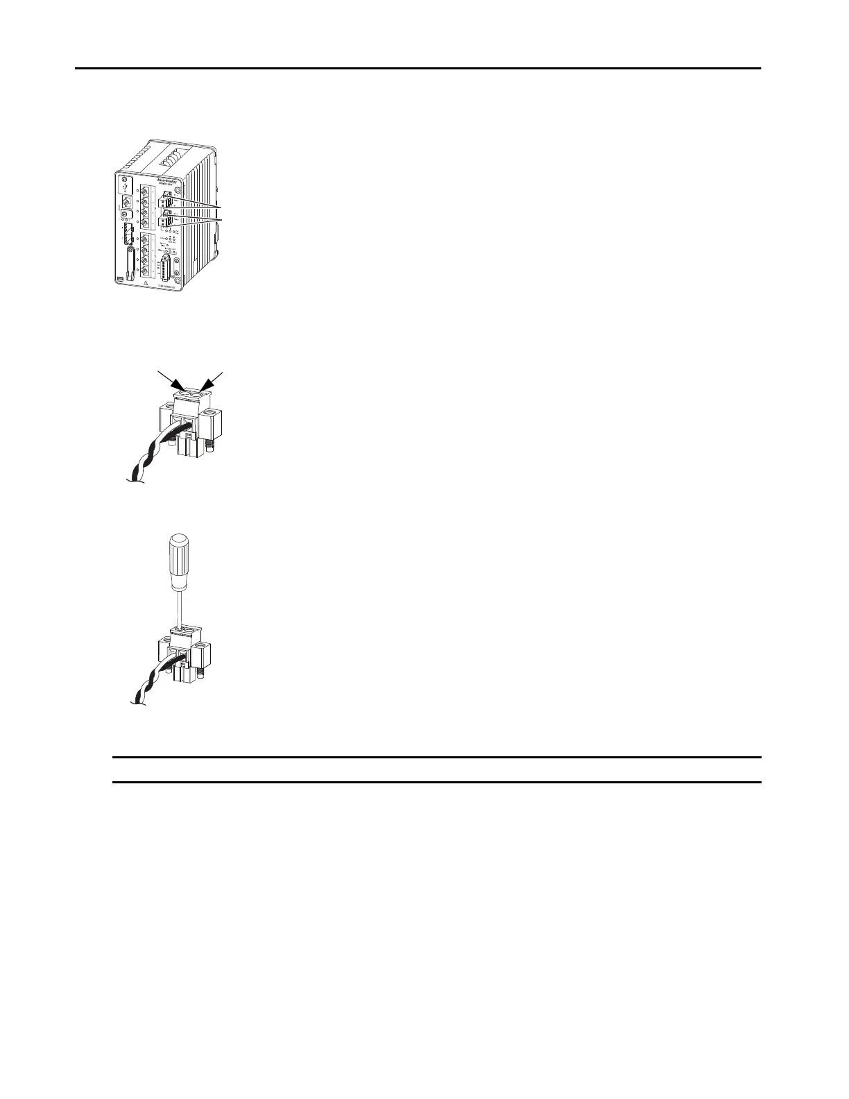
5. Remove the two captive screws that attach the power connector to the switch, and remove the power connector.
Remove both connectors if you are connecting to two power sources.
6. On the power connector, insert the exposed part of the positive wire into the connection labeled “+” and the exposed part of the return wire
into the connection labeled “–”.
Make sure that you cannot see any wire lead. Only wire with insulation can extend from the connector.
7. Use a ratcheting torque screwdriver to torque the power connector captive screws above the installed wire leads to 0.565 N•m (5 in•lb), the
maximum recommended torque.
8. Connect the other end of the positive wire to the positive terminal on the DC power source.
9. Connect the other end of the return wire to the return terminal on the DC power source.
To test the switch, one power connection is sufficient. To install the switch with a second power source, repeat the preceding steps for the second
power connector.
Install the Power Connectors on the Switch
1. Insert one power connector into the Pwr A receptacle on the switch front panel, and the other into the Pwr B receptacle.
2. Use a screwdriver to tighten the captive screws on the sides of each power connector.
3. Use a ratcheting torque screwdriver to torque the power connector captive screws to 0.226 N•m (2 in•lb), the maximum recommended
torque.
4. To apply power to a switch that is directly connected to a DC power source, locate the circuit breaker on the panel board that services the
DC circuit. Then switch the circuit breaker to the On position.
IMPORTANT On switches that support PoE, do not connect the negative (return) terminal of the DC power source to earth ground.
Power Connectors
Positive Connection
Return Connection
 Loading...