Rockwell Automation Publication 1783-IN013B-EN-P - December 2019 9
Stratix 5800 Ethernet Managed Switches
3. Insert the ground wire into the ring terminal lug and use a crimping tool to crimp the terminal to the wire.
If two ring terminals are being used, repeat this action for a second ring terminal.
4. Slide the ground screw through the ring terminal.
5. Insert the ground screw into the functional ground screw opening on the front panel.
6. Use a ratcheting torque screwdriver to tighten the ground screws and ring terminal lugs to the front panel to 0.51 N•m (4.5 lb•in).
The torque must not exceed 0.51 N•m (4.5 lb•in).
7. Attach the other end of the ground wire to a grounded bare-metal surface, such as a ground bus or a grounded DIN rail.
Wire the DC Power Source
The switch meets the voltage dips and interruptions requirements of IEC 61850-3 only when powered by a redundant power supply configuration.
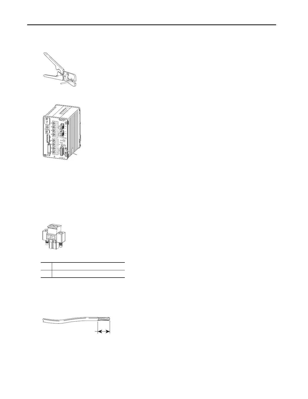
1. Locate the two power connectors on the switch front panel labeled Pwr A and Pwr B.
2. Identify the positive and return DC power connections by using the labels on the switch panel.
3. Measure two strands of twisted-pair copper wire 14 AWG (1.6 mm
2
) long enough to connect to the DC power source.
4. Use a wire-stripping tool to strip each of the two wires to 6.3 mm (0.25 in.) ± 0.5 mm (0.02 in.).
Do not strip more than 6.8 mm (0.27 in.) of insulation from the wire. Stripping more than the recommended amount of wire can leave
exposed wire from the connector after installation.
DC + Positive DC power connection
DC – Return DC power connection
Ground-lug Screw
6.3 mm (0.25 in.) ± 0.5 mm (0.02 in.)
 Loading...