12 Rockwell Automation Publication 1783-IN013B-EN-P - December 2019
Stratix 5800 Ethernet Managed Switches
6. Repeat steps 2…5 to insert the input and output wires of one more external alarm device into the alarm connector.
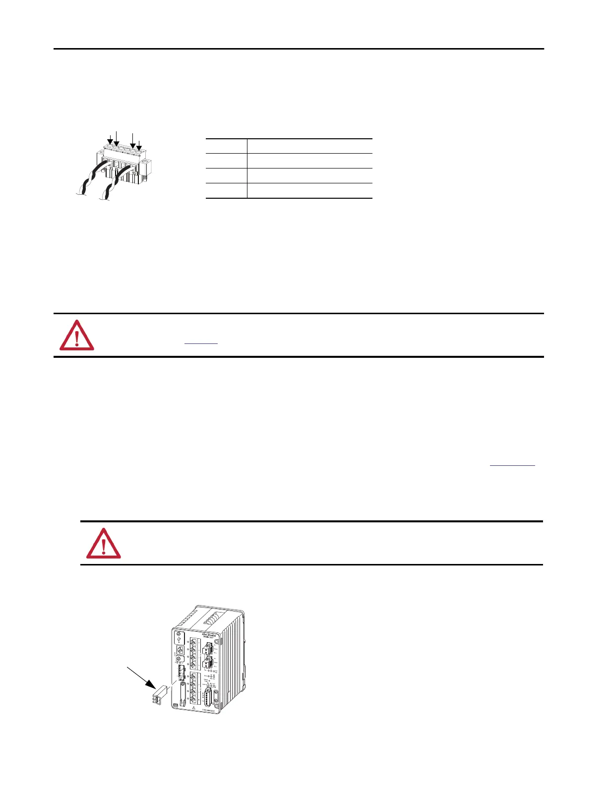
The following figure shows the completed wiring for two external alarm devices. The first alarm device circuit is wired as an alarm input
circuit. The IN1 and REF connections complete the circuit. The second alarm device circuit is wired as an alarm output circuit that works
on a normally open contact basis. The N.O. and COM connections complete the circuit.
Install the Alarm Relay Connector on the Switch
1. Insert the alarm relay connector into the receptacle on the switch front panel.
2. Use a ratcheting torque screwdriver to tighten the captive screws on the sides of the alarm relay connector.
Install or Remove and SFP Module
On switch catalog numbers that support communication over fiber-optic cable, SFP modules are inserted into SFP module slots on the front of the
switch. These field-replaceable modules provide the uplink optical interfaces, send (TX) and receive (RX).
You can use any combination of compatible SFP modules:
• Each SFP module must be of the same type as the SFP module on the other end of the cable. The cable must not exceed the stipulated cable
length for proper communications.
• The overall temperature rating of the combined modules (switch and installed SFP modules) is limited to the lowest maximum temperature
rating and the highest minimum temperature rating.
• For cable length and temperature specifications, see the Stratix Ethernet Device Specifications Technical Data, publication
1783-TD001.
1. Attach an ESD-preventive wriststrap to your wrist and to a grounded bare metal surface.
2. To install an SFP module, do the following:
a. Grasp both sides of the SFP module and align the module sideways in front of the slot opening.
b. Insert the SFP module into the slot as shown in the following figure until you feel the connector on the module snap into place in the
rear of the slot.
c. Remove the dust plugs from the SFP module optical ports, store them for later use.
ATTENTION: Use SFP modules from only Rockwell Automation. For details about supported modules, see the Stratix Ethernet Device Specifications
Technical Data, publication
1783-TD001.
ATTENTION: If the SFP module cannot be fully inserted, stop! Do not force the module into the slot. Rotate the SFP module 180° and try again.
1
3
2
4
1 External device connection 1 (IN1)
2 External device connection 2(REF)
3 COM wired connection
4 N.O. wired connection
 Loading...