8 Rockwell Automation Publication 1783-IN013B-EN-P - December 2019
Stratix 5800 Ethernet Managed Switches
Mount the Switch on a DIN Rail
The switch ships with a spring-loaded latch on the rear panel for a mounting on a DIN rail.
To help prevent excessive side-to-side movement of the unit, we recommend that you install DIN rail stop plates, such as mouser part numbers
653-PFP-M, 651-1201662 or 845-CA402. You can install these end stops on one or both sides of the device to limit excessive side to side movement
that typically occurs in high vibration environments.
You can mount the switch as a standalone device on the DIN rail or with the expansion modules already connected. You must connect an expansion
module to the switch before you mount the switch on the DIN rail.
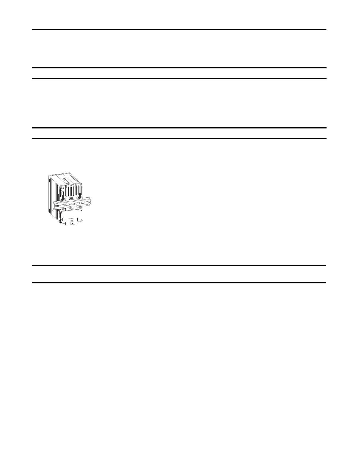
1. Position the rear panel of the switch directly in front of the DIN rail.
Be sure that the DIN rail fits in the space between the two hooks near the top of the switch and the spring-loaded latch near the bottom.
2. Hold the bottom of the switch away from the DIN rail and place the two hooks on the back of the switch over the top of the DIN rail.
3. To cause the latch at the bottom rear of the switch to move down and snap into place, push the switch toward the DIN rail.
Ground the Switch and Expansion Module
To make sure that the equipment is reliably connected to earth ground, follow the grounding procedure instructions, and use a UL Listed ring
terminal lug suitable for number 10 AWG wire.
Use at least a 10 AWG or 2.6 mm
2
conductor to connect to the external grounding screw.
The ground lug is not supplied with the switch. You can use one of these options:
• Single ring terminal
• Two single ring terminals
• Ring terminal on expansion module
1. To remove the ground screw from the front panel of the switch or expansion module, use a standard Phillips screwdriver or a ratcheting
torque screwdriver with a Phillips head.
Store the ground screw for later use.
2. Use the manufacturers guidelines to determine the wire length to be stripped.
IMPORTANT The device is designed to mount on a DIN rail that conforms to Standard EN50022.
IMPORTANT The switch must be mounted in an upright orientation, as shown in these instructions. Alternative mounting orientations are not supported.
IMPORTANT Do not rely on the switch ground for an expansion module. When an expansion module is connected, it must be grounded using the screw on the expansion
module. This is an EMC ground and not a safety ground, unlike the one on the main chassis.
 Loading...