Rockwell Automation Publication 1783-IN013B-EN-P - December 2019 7
Stratix 5800 Ethernet Managed Switches
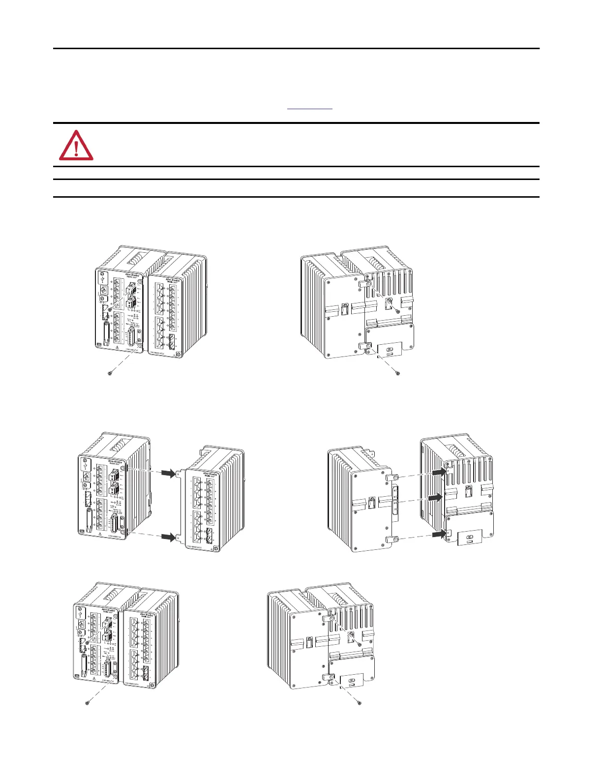
Connect an Expansion Module
If you have an expandable switch model, you can connect one expansion module. For switch and expansion module compatibility restrictions, see
the Stratix Ethernet Device Specifications Technical Data, publication
1783-TD001.
1. Remove the two screws securing the side cover plate to the switch.
2. Remove the two screws from the front of the expansion chassis and the two screws from the rear of the base.
3. Align the tabs on the top and bottom-left front of the expansion module with the slots on the top and bottom-right side of the switch.
4. Align the tabs on the top and bottom-left rear of module and the holes at the top and bottom-right rear of switch.
5. Press the expansion module and the switch together, so that the electrical connections engage and the screw holes align.
6. Secure the four flathead Phillips screws with 0.565 N•m (5…6 in•lbs) torque.
WARNING: Do not attempt to connect or separate an expansion module from a base switch in a hazardous environment. Doing so can produce a spark and
create an explosion hazard.
IMPORTANT Be sure that power is removed from the switch before you add an expansion module.
 Loading...